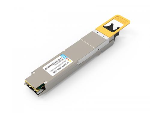

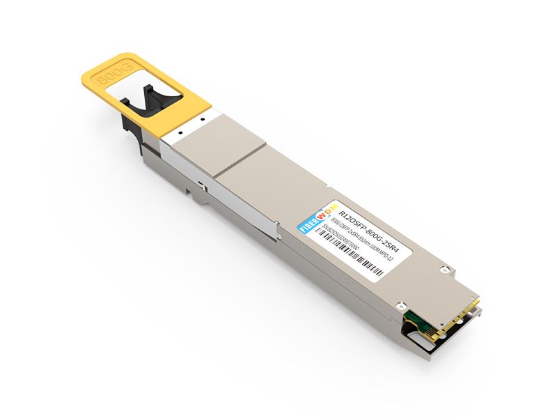
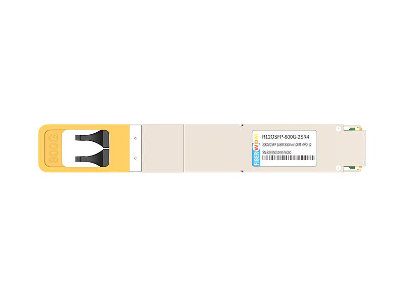
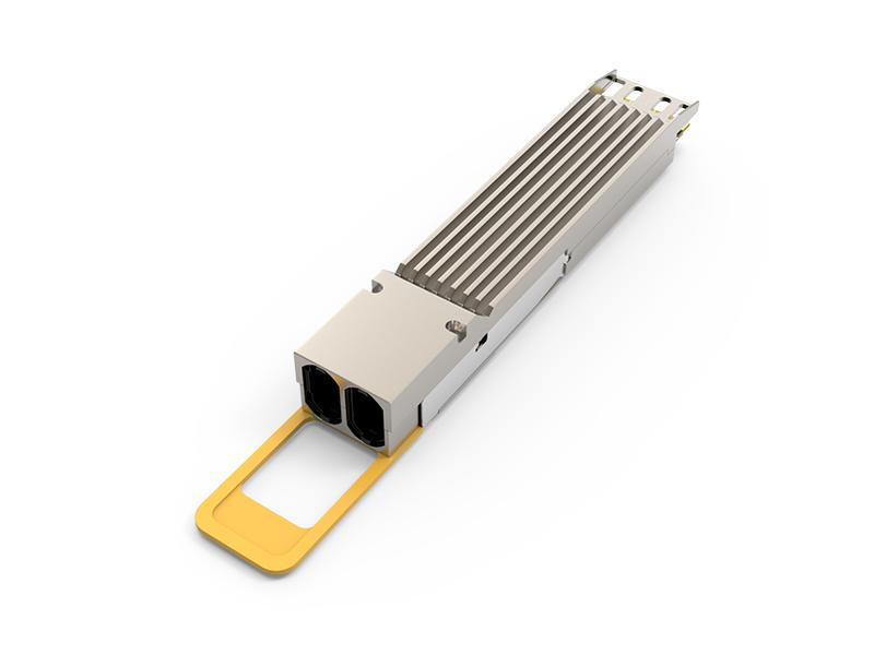
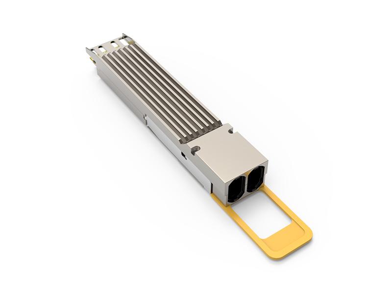
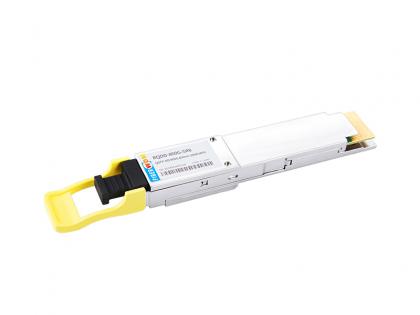
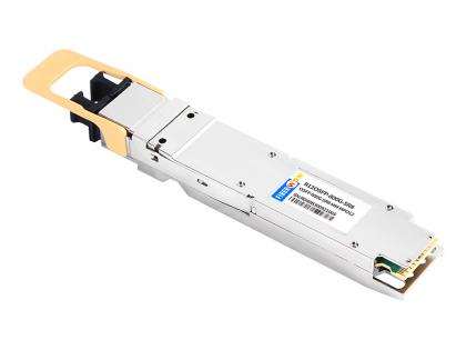
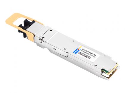
This product is a 800Gb/s OSFP 2xSR4 optical module designed for 100m optical communication applications. The module converts 8 channels of 100Gb/s (PAM4) electrical input data to 8 channels of parallel optical signals, each capable of 100Gb/s operation for an aggregate data rate of 800Gb/s.
On the receiver side, the module converts 8 channels of parallel optical signals of 100Gb/s each channel for an aggregate data rate of 800Gb/s into 8 channels of 100Gb/s (PAM4) electrical output data.
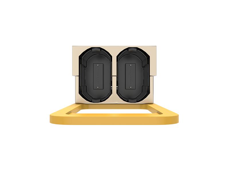
An optical fiber cable with dual MPO-12 connector can be plugged into the OSFP 800G SR8 module receptacle. Host FEC is required to support up to 100m fiber transmission.
800G OSFP 2xSR4 850nm 100M MPO-12 Optical transceiver
R12OSFP-800G-2SR4
Features
Standards
Applications
Absolute Maximum Ratings
| Parameter | Symbol | Min | Max | Units |
| Storage Temperature Range | TSTG | -40 | +85 | ℃ |
| Supply Voltage | VCC | 0 | 4 | V |
| Relative Humidity | RH | 5% to 85% | ||
| - | - | non-condensing | ||
Operating Conditions
| Parameter | Symbol | Min | Max | Units |
| Case Temperature- Operating | TCASE | 0 | 70 | ℃ |
| Supply Voltage | Vcc | 3.135 | 3.465 | V |
| Power Consumption | PDISS | - | 14 | W |
| Pre-FEC Bit Error Ratio | - | - | 2.4x10⁻⁴ | - |
| Link Distance over OM3 | - | 0.5 | 60 | M |
| Link Distance over OM4 | - | 0.5 | 100 | M |
Transmitter Optical Specifications
| Transmitter Parameter | Min | Typical | Max | Unit |
| Signaling rate each lane | 53.125±100ppm |
GBd |
||
| Lane Wavelength Range | - | 850 | - | nm |
| RMS Spectral width | - | 0.6 | nm | |
| Modulation Format | PAM4 | |||
| Average Optical Power per lane | -4.6 | 4 | dBm | |
| Outer Optical Modulation Amplitude (OMAouter), each lane for TDECQ<=1.8dB for 1.8<TDECQ<=4.4dB |
-2.6 |
- | 3.5 |
dBm |
| Outer Optical Modulation Amplitude (OMAouter), each lane for TECQ<=1.8dB for 1.8<TECQ<=4.4dB |
-2.6 |
- | 3.5 |
dBm |
| Transmitter and Dispersion Eye Closure for PAM4, each Lane | - | - | 4.4 | dB |
| Transmitter Eye Closure for PAM4(TECQ), each Lane | - | - | 4.4 | dB |
| Extinction Ratio | 2.5 | - | dB | |
| Transmitter excursion ,each lane | - | - | 2 | dB |
| Transmitter transition time,each lane | - | - | 17 | Ps |
| Average Launch Power per Lane @ TX Off State | - | - | -30 | dBm |
| Relative Intensity Noise12(OMA) | - | - | -131 | dB/Hz |
| Optical Return Loss Tolerance | - | - | 12 | dB |
| Encircled Flux | >=86% at 19um <=30% at 4.5um |
dB | ||
Receiver Optical Specifications
| Receiver Parameter | Min | Typical | Max | Unit |
|
Signaling rate each lane |
53.125±100ppm |
GBd |
||
|
Lane Wavelength Range |
- | 850 | - |
nm |
| Modulation Format | PAM4 | |||
|
Damage Threshold |
5 | - | - |
dBm |
|
Average Receive Power, each lane |
-6.4 | - | 4 |
dBm |
|
Receiver Power, each lane (OMA) |
- | - | 3.5 |
dBm |
|
Receiver Sensitivity each lane (OMAouter) |
- | - |
-4.6 |
dBm |
|
Receiver reflectance |
- | - | -12 |
dB |
|
Stressed Receiver Sensitivity (OMAouter), each |
- | - | 2 |
dBm |
| Stressed Conditions for Stress Receiver Sensitivity | ||||
|
Stressed Eye Closure for PAM4 (SECQ),Lane under Test |
- | 4.4 | - |
dB |
|
OMAouter of each Aggressor Lane |
- | 3.5 | - |
dBm |
Receiver Thresholds for Loss of Signal (LOS)
|
Parameter |
Min |
Typical |
Max |
Unit |
|
RX_LOS_Assert Min/Max |
-15.0 |
- | - |
dBm |
|
RX_LOS_De-Assert Min/Max |
- | - | -8.9 |
dBm |
|
RX_LOS_Hysteresis |
- | 1.5 | - |
dB |
Digital Diagnostic Monitoring Specifications
|
Parameters |
Unit |
Specification |
| Temperature Monitor absolute error | ℃ |
± 3 |
|
Supply Voltage Monitor absolute error |
% |
± 5 |
|
I_bias Monitor absolute error |
% |
± 10 |
|
Received Power (Rx) Monitor absolute error |
dB |
± 3.0 |
|
Transmit Power (Tx) Monitor absolute error |
dB |
± 3.0 |
Low Speed Electrical signal
| Parameter | Symbol | Min | Max | Units | Condition |
|
SCL and SDA |
VOL |
0 | 0.4 | V |
IOL(max)=3.0mA for fast mode,20mA for Fast-mode plus |
|
VOH |
Vcc-0.5 |
Vcc+0.3 |
V | ||
|
SCL and SDA |
VIL |
-0.3 |
Vcc*0.3 |
V | - |
|
VIH |
Vcc*0.7 |
Vcc +0.5 |
V | - | |
|
Capacitance for SCL and SDA I/O pin |
Ci | - | 14 |
pF |
- |
|
Total bus cpacitive load for SCL and SDA |
Cb | - | 100 |
pF |
3.0k Ohms Pull up resistor,max |
| - | - | 200 |
pF |
1.6k Ohms Pull up resistor,max |
|
|
LPMode/TxDis,Reset and ModeSeIL |
VIL |
-0.3 | 0.8 | V |
|Iin| </= 125uA for Vin < Vcc |
|
VIH |
2 |
Vcc + 0.3 |
V | ||
|
IntL/RxLOS |
VOL |
0 | 0.4 | V |
IOL=2.0mA |
|
VOH |
VCC - 0.5 |
VCC + 0.3 |
V |
10k ohms pull-up to Host Vcc |
|
|
ModPrsL |
VOL |
0 | 0.4 | % |
IOL=2.0mA |
|
VOH |
- | - | dB |
ModPrsL can be implemented as a short-circuit to GND on the module |
High Speed Electrical signal
|
Parameter |
Min |
Typical |
Max |
Unit |
|
Receiver electrical output characteristics at TP4 |
||||
|
Signaling rate per lane |
- |
53.125 |
- |
GBd |
|
AC common-mode output voltage(RMS) |
- | - | 17.5 | mV |
|
Differential peak-to-peak output voltage |
- | - | 900 |
mV |
|
Near-end ESMW (Eye symmetry mask width) |
- | TBD | - | UI |
|
Near-end Eye height, differential |
24 | - | - | mV |
|
Near-end vertical eye closure |
- | - | 7.5 |
dB |
|
Far-end ESMW (Eye symmetry mask width) |
- | TBD | - | UI |
|
Far-end Eye height, differential |
24 | - | - | mV |
|
Far-end vertical eye closure |
- | - | 7.5 |
dB |
|
Far-end pre-cursor ISI ratio |
- | TBD | - | % |
|
Common mode to differential conversion return loss |
802.3ck 120G-1 |
dB |
||
|
Effective return loss |
TBD | - | - |
dB |
|
Differential termination mismatch |
- | - | 10 | % |
|
Transition time (min, 20% to 80%) |
- | TBD | - | ps |
|
DC common mode voltage |
-350 | - | - | mV |
|
Transmitter electrical input characteristics at TP1 |
||||
|
Signaling rate, per lane |
- |
53.125 |
- |
GBd |
|
Differential pk-pk input voltage tolerance |
900 | 2850 | mV | |
|
Common-mode to differential return loss |
802.3ck Equation(120G-1) |
- | - | - |
|
Effective return loss |
TBD | - | - | - |
|
Differential termination mismatch |
- | - | 10 | - |
|
Module stressed input test |
See 120G.3.4.1 |
% |
||
|
Single-ended voltage tolerance range |
-0.4 |
- | 3.3 | V |
|
DC common-mode voltage |
-350 |
- | 2850 | mV |
Module Block Diagram
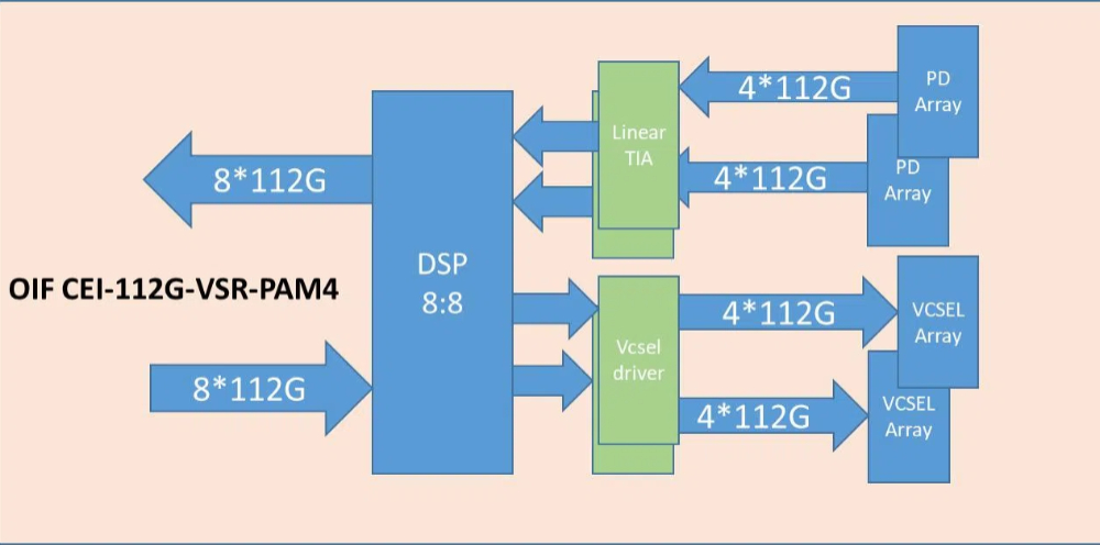
Figure 1. Module Block Diagram
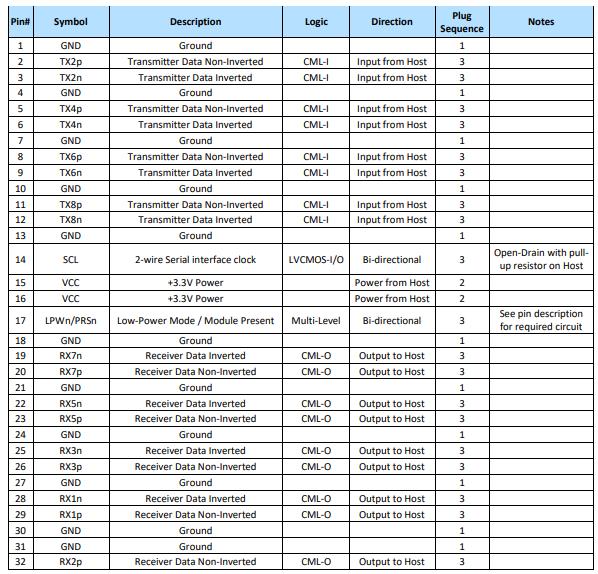
OSFP800 800G 2xSR4
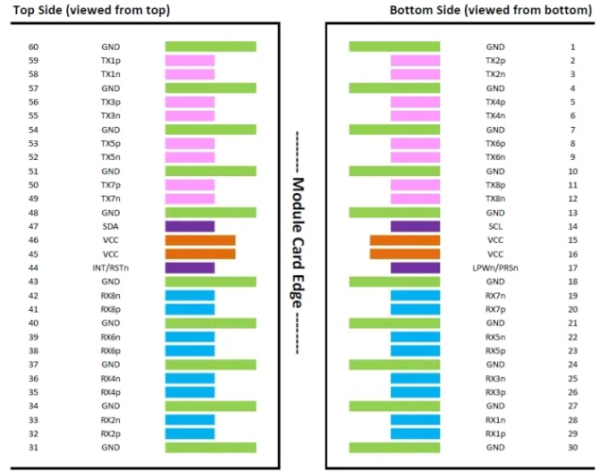
Figure 2. OSFP800 800G contact assignment
Module contact definition
Optical interface
The dual MPO-12 connectors for OSFP800 2xSR4.
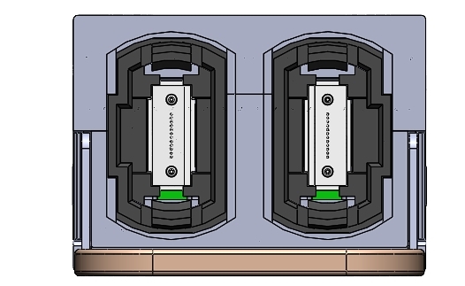
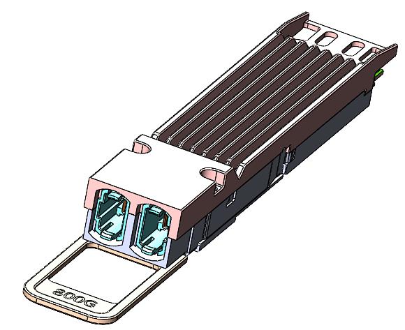
Figure 3. Optical lane assignments
Mechanical Specifications
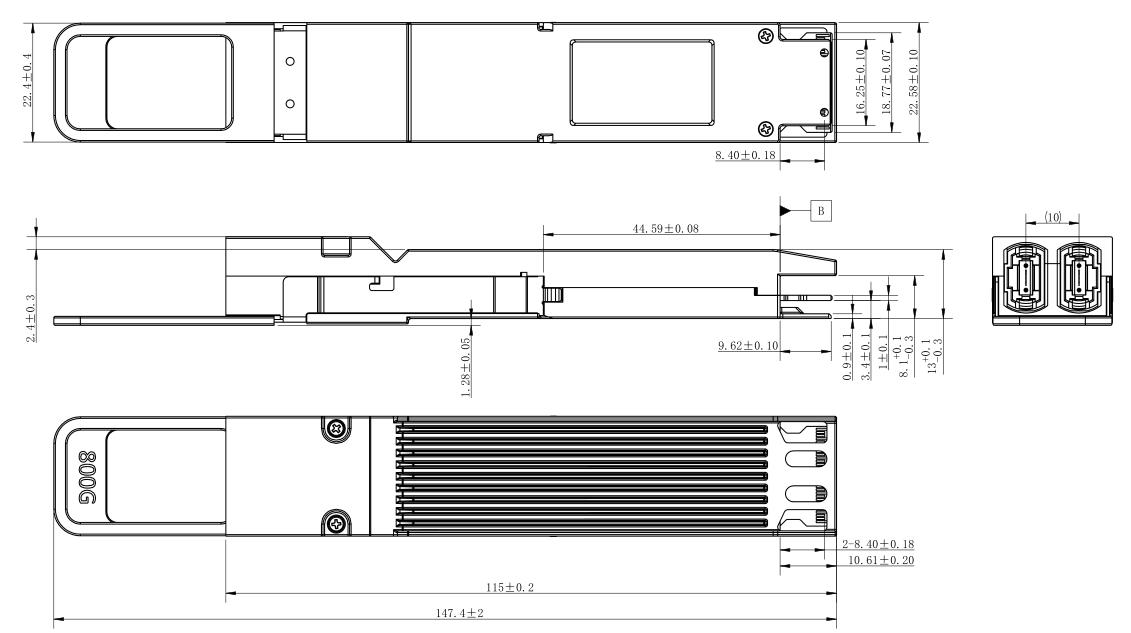
Figure 4. Mechanical Dimensions
Ordering information
|
Part Number |
Description |
|
R12OSFP-800G-2SR4 |
OSFP800 800G 2xSR4 Optical transceiver |
Want to know about this product?
If you are interested in our products and want to know more details,please leave a message here,we will reply you as soon as we can.
 800G QSFP-DD SR8 850nm 100m MPO-16 APC
 800G OSFP SR8 MM MPO12 Optical Transceiver IB
 800G OSFP DR8 SM MPO12 Optical Transceiver IB
 800G QSFP-DD 2FR4 PAM4 1310nm 2km DOM Dual CS SMF Optical Transceiver Module
 800G QSFP-DD 2xLR4
 800G QSFP-DD DR8
 800G QSFP-DD DR8+
 800G QSFP-DD DR8++

Address : Room 901, Building 6, JD Smart Industrial Park, No. 128, Juhua Stone Avenue, Huashan Town, Huadu District, Guangzhou City
Tel : +86 15989256178
Whatsapp : +86 15914235380
Email : sales@fiberwdm.com


