
Features
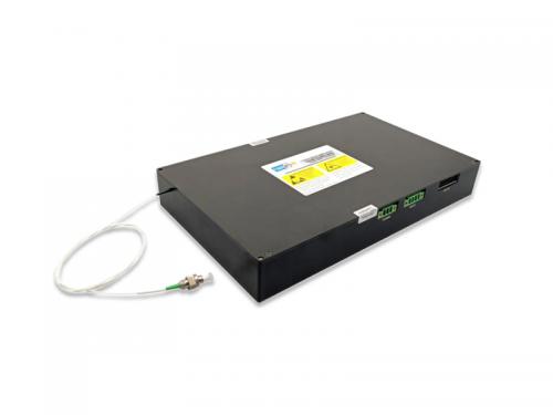
DTS Integrated Module
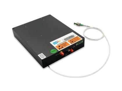
Distributed Temperature Fiber Sensing(DTS) module based on the Raman scattering principle, a single optical fiber as a transmission, the use of optical fiber inside the Stokes light and anti-Stokes light on the temperature of the different degree of sensitivity to temperature resolution, widely used in electric power, cable temperature monitoring, oil and gas pipeline temperature measurement and detection, subway, tunnels, buildings and other fire detection.
FIBERWDM for distributed fiber optic temperature sensing field, launched the DTS integrated module with data acquisition card, internal integration of DTS Raman light source, WDM, APD and data acquisition card, the network port directly output temperature information. And the module is highly integrated, with small size and high reliability.
|
Features
|
Applications
|
Spatial Resolution

Temperature Accuracy

Product Specification
| Parameters | Multi-mode | High Accuracy | Single-mode | Unit |
|
Model |
FW-DTS-15-1.0 |
FW-DTS-05-0.3 |
FW-DTS-25-5.0 |
- |
|
Max Sensing Distance |
15 | 5 | 25 | km |
|
Sampling Resolution |
0.4 | 0.1 | 0.4 | m |
|
Spatial Resolution |
1.0 | 0.3 | 5 | m |
|
Position Accuracy |
2 | 0.4 | 5.0 | m |
|
Measurement Time |
6 | 6 |
180~300 |
s |
|
Temperature Accuracy |
±2 | ±3 | ℃ | |
|
Fiber Type |
MM | SM | - | |
|
Temperature Resolution |
0.1 | ℃ | ||
|
Temperature Range |
-20 ~ +120 |
℃ | ||
|
Note: 1)The unit can be used with optical switch, such as 1*4 or 1*8 2)Wider temperature measurement range with special fiber optic |
||||
|
Parameters |
Indicator |
Remark |
|
|
Electrical |
Power Supply |
DC +12V/GND |
|
|
Power Consumption |
<25W |
Full-temperature |
|
|
Mechanical |
Dimensions |
250*150*35mm |
|
|
Pigtail Type |
62.5μm MM/SM |
Customized |
|
|
Communication |
Output |
RS485 |
Modbus |
|
RJ45 |
UDP/TCP-IP |
||
|
Interface |
Output temperature |
||
|
Parameters |
Min |
Max |
Unit |
|
Working Temperature |
-10 | +50 | ℃ |
|
Storage Temperature |
-40 | +70 | ℃ |
|
Relative Humidity |
5 | 90 | % |
Mechanical

For ordering information and custom solutions, please contact us: sales@fiberwdm.com
Want to know about this product?
If you are interested in our products and want to know more details,please leave a message here,we will reply you as soon as we can.
 DAS Integrated Optical Module(Raman)
 DAS Integrated Optical Module
 DVS Integrated Optical Module
 Atmospheric Coherent Detection LiDAR Pulsed Light Source
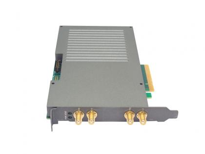 250MSps Dual-channel High-speed Data Acquisition Card
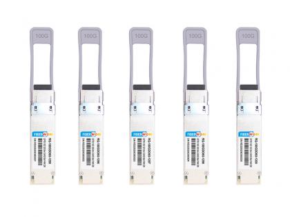 QSFP28 100G O-Band DWDM 60KM SM LC Transceiver
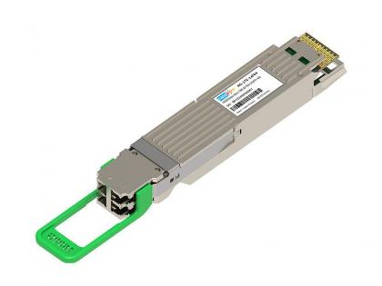 1.6T OSFP-XD 2*FR4
 100G QSFP28 to 2x 50G QSFP28 AOC Transceiver

Address : Room 901, Building 6, JD Smart Industrial Park, No. 128, Juhua Stone Avenue, Huashan Town, Huadu District, Guangzhou City
Tel : +86 15989256178
Whatsapp : +86 15914235380
Email : sales@fiberwdm.com


