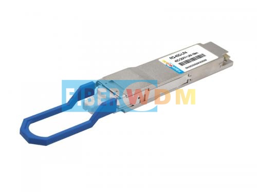

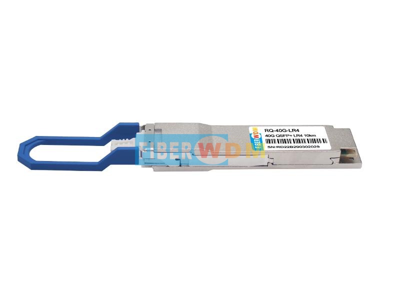
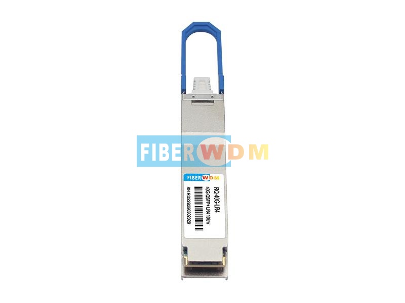
40G QSFP LR4 optical transceiver module, support 40Gb/s and up to 10 km transmission on SM fiber, it works in high-speed IDC connection solutions, and so on.
Features
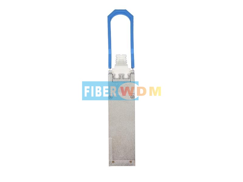
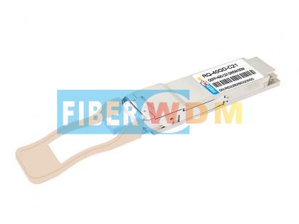
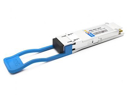
40G QSFP+ LR4 10Km 1310nm LC OpticalTransceiver
The QSFP+ 40G LR4 RQ-40G-LR4 is a transceiver module designed for10km optical communication applications. The design is compliant to 40GBASE-LR4 of the IEEE P802.3ba standard. The module converts 4 inputs channels (ch) of 10Gb/s electrical data to 4 CWDM optical signals, and multiplexes them into a single channel for 40Gb/s optical transmission. Reversely, on the receiver side, the module optically de-multiplexes a 40Gb/s input into 4 CWDM channels signals, and converts them to 4 channel output electrical data.
Absolute Maximum Ratings
|
Parameter |
Symbol |
Min. |
Typical |
Max. |
Unit |
|
StorageTemperature |
TS |
-40 |
|
+85 |
°C |
|
SupplyVoltage |
VCCT, R |
-0.5 |
|
4 |
V |
|
RelativeHumidity |
RH |
0 |
|
85 |
% |
Recommended Operating Environment
|
Parameter |
Symbol |
Min. |
Typical |
Max. |
Unit |
|
Case operatingTemperature |
TC |
0 |
|
+70 |
°C |
|
Supply Voltage |
VCCT, R |
+3.13 |
3.3 |
+3.47 |
V |
|
Supply Current |
ICC |
|
|
900 |
mA |
|
Power Dissipation |
PD |
|
|
3 |
W |
Electrical Characteristics(TOP = 0 to 70 °C, VCC= 3.13 to 3.47 Volts
|
Parameter |
Symbol |
Min |
Typ |
Max |
Unit |
Note |
|
Data Rate per Channel |
|
- |
10.3125 |
11.2 |
Gbps |
|
|
Power Consumption |
|
- |
2.5 |
3.5 |
W |
|
|
Supply Current |
Icc |
|
0.75 |
1.0 |
A |
|
|
Control I/O Voltage-High |
VIH |
2.0 |
|
Vcc |
V |
|
|
Control I/O Voltage-Low |
VIL |
0 |
|
0.7 |
V |
|
|
Inter-Channel Skew |
TSK |
|
|
150 |
Ps |
|
|
RESETL Duration |
|
|
10 |
|
Us |
|
|
RESETL De-assert time |
|
|
|
100 |
ms |
|
|
Power On Time |
|
|
|
100 |
ms |
|
|
Transmitter |
||||||
|
Single Ended Output Voltage Tolerance |
|
0.3 |
|
4 |
V |
1 |
|
Common mode Voltage Tolerance |
|
15 |
|
|
mV |
|
|
Transmit Input Diff Voltage |
VI |
150 |
|
1200 |
mV |
|
|
Transmit Input Diff Impedance |
ZIN |
85 |
100 |
115 |
|
|
|
Data Dependent Input Jitter |
DDJ |
|
0.3 |
|
UI |
|
|
Receiver |
||||||
|
Single Ended Output Voltage Tolerance |
|
0.3 |
|
4 |
V |
|
|
Rx Output Diff Voltage |
Vo |
370 |
600 |
950 |
mV |
|
|
Rx Output Rise and Fall Voltage |
Tr/Tf |
|
|
35 |
ps |
1 |
|
Total Jitter |
TJ |
|
0.3 |
|
UI |
|
Note:
1. 20~80%
Optical Parameters(TOP = 0 to 70°C, VCC = 3.0 to 3.6 Volts)
|
Parameter |
Symbol |
Min |
Typ |
Max |
Unit |
Ref. |
|
Transmitter |
||||||
|
Wavelength Assignment |
L0 |
1264.5 |
1271 |
1277.5 |
nm |
|
|
L1 |
1284.5 |
1291 |
1297.5 |
nm |
|
|
|
L2 |
1304.5 |
1311 |
1317.5 |
nm |
|
|
|
L3 |
1324.5 |
1331 |
1337.5 |
nm |
|
|
|
Side-mode Suppression Ratio |
SMSR |
30 |
- |
- |
dB |
|
|
Total Average Launch Power |
PT |
- |
- |
4 |
dBm |
|
|
Average Launch Power, each Lane |
|
-6 |
- |
1 |
dBm |
|
|
Difference in Launch Power between any two Lanes (OMA) |
|
- |
- |
4 |
dB |
|
|
Optical Modulation Amplitude, each Lane |
OMA |
-5 |
|
+2 |
dBm |
|
|
Launch Power in OMA minus Transmitter and Dispersion Penalty (TDP), each Lane |
|
-5 |
- |
|
dBm |
|
|
TDP, each Lane |
TDP |
|
|
2.3 |
dB |
|
|
Extinction Ratio |
ER |
3.5 |
- |
- |
dB |
|
|
Transmitter Eye Mask Definition {X1, X2, X3, Y1, Y2, Y3} |
|
{0.25, 0.4, 0.45, 0.25, 0.28, 0.4} |
|
|
|
|
|
Optical Return Loss Tolerance |
|
- |
- |
20 |
dB |
|
|
Average Launch Power OFF Transmitter, each Lane |
Poff |
|
|
-30 |
dBm |
|
|
Relative Intensity Noise |
Rin |
|
|
-128 |
dB/HZ |
1 |
|
Optical Return Loss Tolerance |
|
- |
- |
12 |
dB |
|
|
Receiver |
||||||
|
Damage Threshold |
THd |
5 |
|
|
dBm |
1 |
|
Average Power at Receiver Input, each Lane |
R |
-14 |
|
3 |
dBm |
|
|
Receive Electrical 3 dB upper Cut off Frequency, each Lane |
|
|
|
12.3 |
GHz |
|
|
RSSI Accuracy |
|
-2 |
|
2 |
dB |
|
|
Receiver Reflectance |
Rrx |
|
|
-26 |
dB |
|
|
Receiver Power (OMA), each Lane |
|
- |
- |
3.5 |
dBm |
|
|
Receive Electrical 3 dB upper Cutoff Frequency, each Lane |
|
|
|
12.3 |
GHz |
|
|
LOS De-Assert |
LOSD |
|
|
-15 |
dBm |
|
|
LOS Assert |
LOSA |
-25 |
|
|
dBm |
|
|
LOS Hysteresis |
LOSH |
0.5 |
|
|
dB |
|
Note
1. 12dB Reflection
Order information
|
Product Number |
Data Rate(Gb/s) |
Wavelength(nm) |
Reach(km) |
LD |
Tx Power(dBm) |
PD |
Rx Sens(dBm) |
Temperature(℃) |
|
RQ-40G-LR4 |
40 |
CWDM 4 |
10 |
DFB |
-6~1 |
PIN |
<-14 |
0~70 |
Want to know about this product?
If you are interested in our products and want to know more details,please leave a message here,we will reply you as soon as we can.
 40Gs QSFP+ SR4 100m 850nm MPO Optical Transceiver
 40G QSFP+ ER4 40Km 1310nm LC Optical Transceiver
 40GBASE-SR Bi-Directional QSFP+ 850/900nm 100m DOM LC MMF Optical Transceiver Module
 Single Wave 40G DWDM QSFP+ PAM4 Dual LC Transceiver
 40G QSFP+ ZR4 80Km 1310nm LC Optical Transceiver
 40G QSFP+ EZR4 100Km 1550nm LC Optical Transceiver
 40G QSFP+ ER4+ 60km DDM Optical Transceiver
 40G QSFP+ LR4 10Km Single mode LC Optical Transceiver (Industrial)

Address : Room 901, Building 6, JD Smart Industrial Park, No. 128, Juhua Stone Avenue, Huashan Town, Huadu District, Guangzhou City
Tel : +86 15989256178
Whatsapp : +86 15914235380
Email : sales@fiberwdm.com


