China 200G 400G DCI supplier
  • DWDM filter
    Ultra Mini DWDM
    Features Low insertion loss. High wavelength accuracy Extended temperature range Excellent thermal stability Extremely small size Applications DWDM Systems Telecom networks Metro Area Networks Broadband Networks PON Networks
  • CWDM filter
    CCWDM Compact CWDM Mux/Demux Module
    Features Low insertion loss. High wavelength accuracy Temperature range: -40 to 85℃ Excellent thermal stability Extremely small size Applications CWDM Systems Telecom networks Metro Area Networks Broadband Networks PON Networks
  • Optical transport network
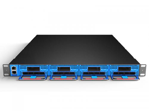
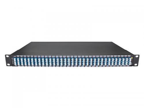
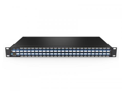
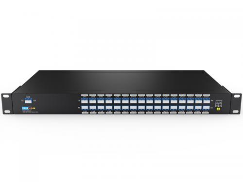
    4x400G DCI BOX, 16*100G 1.6T transmission 1U Rack
    Product Features:   Max support 16x100G for client side, 8x200G or 4x400G for line side in transmission. Total max is 1.6Tbps(3.2Tbps on bidirectional) in 1U device. Achieve higher transfer capacity through device stacking. Maximum up to 19.2Tbps (200G*96ch@50GHz) or 25.6Tbps (400G*64 75GHz or 400G*48 100GHz) 1U chassis modular design, single board adopts hot-swappable design, supports smooth upgrade, and can flexibly expand or delete services according to needs. Dual power supply, compatible with AC or DC power supply DC-48V. Complete network management protocol: supports WEB, SNMP, CLI, TLI and other network management interfaces. Support dual network management cards, 1+1 network function.      
  • 100G QSFP28 LR1
    100Gb QSFP28 LR1 10Km Single Lambda 1271/1291/1311/1331nm LC Optical Transceiver
    The 100G LR1 Single Lambda QSFP28 Optical Transceiver Module is designed for use in 100GBASE Ethernet throughput up to 10km over single mode fiber (SMF) using a wavelength of 1290nm or 1270/1290/1310/1330 via duplex LC connectors. So can be used 4x100G QSFP28 CWDM transceiver and one 4CH CWDM MUX(1270~1330nm) up to 400G transmission on two core fiber(SMF), 2-10KM distance between two Data Center Features Up to 106.25Gbps data rate single channel 1x106.25Gbps PAM4 Line side, 4x25.78Gbps NRZ Host side or 4x26.56Gbps NRZ Host side (close Media-side KP1 FEC inside Module) 100Gbps hermetic TOSA with EML (1271,1291, 1311 or 1331nm)and PIN Detector Dual LC optical interface compliant DDM function implemented Maximum link length of 10km on SMF fiber Low power dissipation: <4W International class 1 laser safety certified Operating temperature range: 0C ~ +70 C Compliant with ROHS6
  • 64ch 75G DWDM MUX DEMUX
    75GHz 64CH DWDM MUX DEMUX 1528.68nm-1566.42nm with Monitor Port LC/UPC 1U Rack
    IL<5.5dB, 75GHZ DWDM AAWG Technology Multiplexing of 64 Channels in a Dark Fiber Network 64 * 400G DCI transfer system Passive devices, No Power No Cooling Required Support Metro, Regional and Long Haul DWDM Networks
  • SFP 1.25G DWDM 180KM Transceiver
    SFP 1.25G C17-C61 DWDM 180KM DDM Optical Transceiver
    1.25G SFP optical transceiver module, support 1.25Gb/s and up to 180 km transmission Features: Hot-Pluggable Duplex LC connector Up to 1.25Gb/s data rate 100GHz ITU Grid, C Band DWDM COOLED DFB transmitter, APD photo-detector SMF links up to 180km 2-wire interface for management specifications compliant with SFF 8472 digital diagnostic monitoring interface Power Supply :+3.3V Power consumption
  • 48ch 100Hz DWDM MUX DEMUX
    100Hz 48CH DWDM MUX DEMUX C17-C64 with Monitor and 1310nm Port DUAL FIBER LC/UPC 1U Rack
    1310nm port can support 1G LX/SX, 10G LR, 40G ER4/LR4, 100G LR/ER4/LR4/ZR4; it for Existing Legacy Traffic. Mon port is for network link monitoring or power monitoring, easy troubleshooting without affecting traffic.
  • 32ch 150GHz DWDM MUX DEMUX
    150GHz 32CH DWDM MUX DEMUX DUAL FIBER LC/UPC 1U Rack
    150GHz C-band Flat top 32-Channel Athermal AWG, DWDM MUX DEMUX LC/UPC 1U RACK     Introduction   The 150GHz 32ch DWDM MUX DEMUX operate in C-band. And it meet the following specification over the operating temperature.   Definition Note:    All specifications should be guaranteed at the worst-case polarization state and over the entire operating environmental condition and end of life. The Insertion Loss of a device is defined as the maximum loss at a defined wavelength, taking into account the worst-case polarization state over the full operating temperature range. The Insertion Loss Uniformity of a device is the difference between the insertion loss of the best-case and worst-case channels. The Polarization Dependent Loss of a device is the maximum insertion loss difference between all polarization states at the defined wavelength. The Reference Passband is defined as a band of wavelengths around each center wavelength. It is used in the definition of crosstalk. The Adjacent Isolation of channel is the maximum insertion loss difference from the mean transmission at the ITU grid wavelength to the highest power over the all polarization and the ITU band of two adjacent channels. The Non-adjacent Isolation of channel is the maximum insertion loss difference from the mean transmission at the ITU grid wavelength to the highest power over the all polarization and the ITU band of the non-adjacent channels. The Total Crosstalk of channel is the total cumulative insertion loss difference from the mean transmission at the ITU grid wavelength to the highest power over the all polarization and the ITU band of all other channels including adjacent and non-adjacent channels. The Wavelength Accuracy is defined as the maximum difference between the defined wavelength and the center of measured 3dB passband.   Product Penal                           150GHz DWDM MUX DEMUX 32CH 1U Rack Technical Parameter   Parameter Specification Units Notes Min Type Max Channel Spacing 150 GHz   Nos of Channel 32 Ch   Channel Frequencies ITU Grid THz   Available Channel Frequency Range 191.2   196.7 THz   Channel Passband -60   +60 GHz   -0.48   +0.48 nm   Center Wavelength Accuracy -0.05   +0.05 nm   -6.25   +6.25 GHz   Insertion Loss     5.5 dB @Center Wavelength     6.0 dB Full Bandwidth Passband Ripple     0.6 nm Full Bandwidth Bandwidth @1.5dB 135     GHz   Bandwidth @3.0dB 160     GHz   Bandwidth @20dB     310 GHz   Insertion Loss Uniformity at ITU     1.50 dB   Polarization Dependent Loss     0.5 dB   Adjacent Channel Isolation 13 15   dB   Non-Adjacent Channel Isolation 30 35   dB   Total Cross Talk 11 13   dB   Directivity 50     dB   Return Loss with connectors 40 45   dB   Chromatic Dispersion -20   +20 ps/nm   PMD     0.5 ps   Optical Power Handling of Common Port     24 dBm     Operating Conditions   Parameter   Min Max Units Temperature   -5 70 ℃ Humidity Non-condensing 0 90 % R.H.   Storage Conditions   Parameter   Min Max Units Temperature   -40 85 ℃ Humidity Non-condensing 0 90 % R.H.   Channel Plan 32Port AWG - On grid   The AWG operate in C-band. The channels are as follows Table 1   Channel ITU Frequency Wavelength Channel ITU Frequency Wavelength No. Channel THz nm No. Channel THz nm 1   191.4000 1566.314 17   193.8000 1546.917 2   191.5500 1565.087 18   193.9500 1545.720 3   191.7000 1563.863 19   194.1000 1544.526 4   191.8500 1562.640 20   194.2500 1543.333 5   192.0000 1561.419 21   194.4000 1542.142 6   192.1500 1560.200 22   194.5500 1540.953 7   192.3000 1558.983 23   194.7000 1539.766 8   192.4500 1557.768 24   194.8500 1538.581 9   192.6000 1556.555 25   195.0000 1537.397 10   192.7500 1555.343 26   195.1500 1536.216 11   192.9000 1554.134 27   195.3000 1535.036 12   193.0500 1552.926 28   195.4500 1533.858 13   193.2000 1551.721 29   195.6000 1532.681 14   193.3500 1550.517 30   195.7500 1531.507 15   193.5000 1549.315 31   195.9000 1530.334 16   193.6500 1548.115 32   196.0500 1529.163   Table 2   Channel ITU Frequency Wavelength Channel ITU Frequency Wavelength No. Channel THz nm No. Channel THz nm 1   191.3625 1566.621 17   193.7625 1547.216 2   191.5125 1565.394 18   193.9125 1546.019 3   191.6625 1564.169 19   194.0625 1544.824 4   191.8125 1562.945 20   194.2125 1543.631 5   191.9625 1561.724 21   194.3625 1542...
1 ... 8 9 10 11 12 ... 19

A total of 19 pages

Leave A Message
Leave A Message
If you are interested in our products and want to know more details,please leave a message here,we will reply you as soon as we can.

Home

Products

about

contact