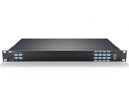
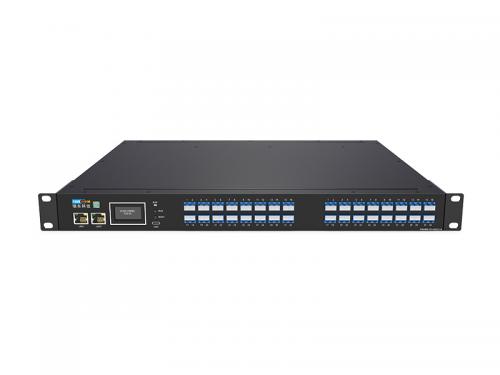
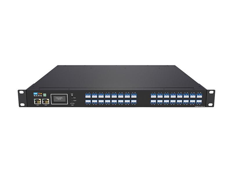
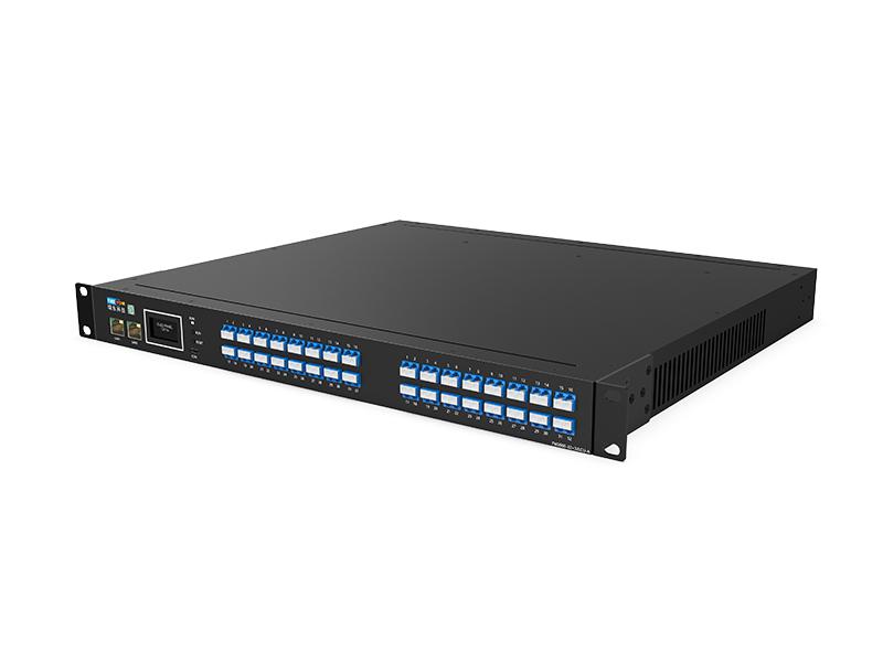
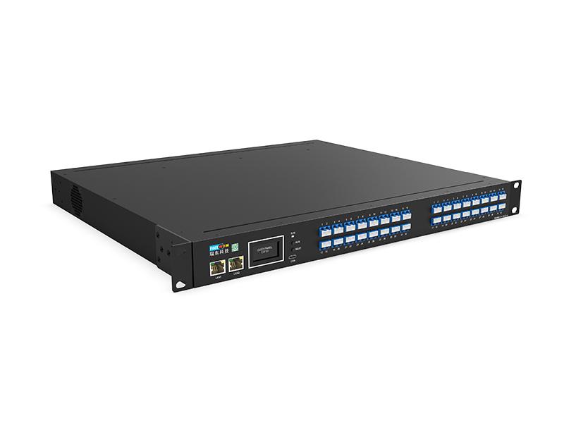
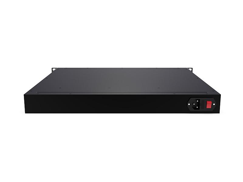
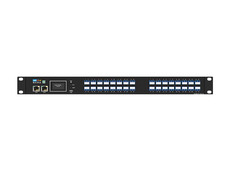

The FW2600-32X32LCU-A rack-mounted optical switching device consists of MEMS optical switches and enables the switching of optical fiber paths among 32 input channels and 32 output channels. The device features an Ethernet RJ45 communication interface, allowing switching to be controlled via a graphical network management interface; it also provides a set of TCP/IP protocol communication commands. Optical switching devices play a critical role in optical communication applications, primarily in multi-channel optical monitoring and switching within optical transmission systems, test and simulation systems, fiber-optic sensing systems, and the commissioning and testing systems for optical components.
32×32 Fiber Optical Switch Single-Mode 1310/1550nm LC/UPC 1U Chassis
The FW2600-32X32LCU-A rack-mounted optical switching device consists of MEMS optical switches and enables the switching of optical fiber paths among 32 input channels and 32 output channels. The device features an Ethernet RJ45 communication interface, allowing switching to be controlled via a graphical network management interface; it also provides a set of TCP/IP protocol communication commands. Optical switching devices play a critical role in optical communication applications, primarily in multi-channel optical monitoring and switching within optical transmission systems, test and simulation systems, fiber-optic sensing systems, and the commissioning and testing systems for optical components.
| name | parameter |
| model | FW2600-32X32LCU-A |
| Cross-switching specifications | 32X32 |
| operating wavelength | 1260~1650 |
| Test wavelength | ≤ 3.5 dB |
| insertion loss | ≤ ±0.05 dB |
| repetitiveness | ≥ 50 dB |
| return loss | ≥ 55 dB |
| Crosstalk | ≤ 0.25 dB |
| Wavelength-dependent loss | ≤ 0.05 dB |
| Polarization-dependent loss | ≤20 ms |
| switching period | SMF-28E |
| Fiber type | ≤500mW |
| Enter optical power | ≥109 |
| life span | LC\UPC |
| Connector type | RJ45 |
| Management port | AC:100~240V |
| working power supply | -10 ~ +60℃ |
| working temperature | -40 ℃ ~ +85 ℃ |
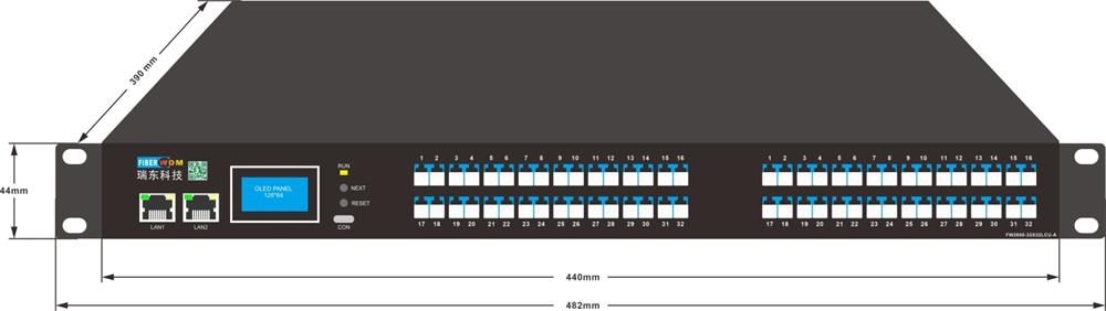
| Chassis type | 19-inch standard 1U rack (482 × 390 × 44) |
Optical path diagram
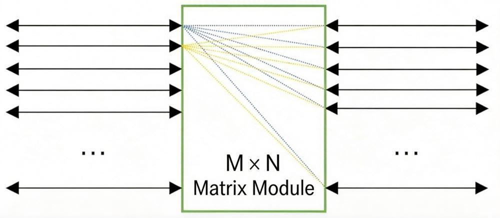
An M×N all-optical switching matrix is formed by cascading M 1×N MEMS optical switches with N 1×M MEMS optical switches, enabling arbitrary switching among M optical signals and N optical signals. The optical switch matrix offers high port density, fast switching speeds, low power consumption, and a flexible, configurable topology.
Note: The input and output optical paths are reversible.
1. Equipment Panel Diagram
front panel

(1) LAN1/LAN2: RJ45 Ethernet interface; device management and communication interface.
(2) LCD display: display of the device IP address and related information.
(3) Next: Flip down to view the button
(4) Reset: Reset button
(5) Run indicator: equipment operation indicator
(6) Con: Console debugging interface
(7) User optical interface: 32×32 LC/UPC.
back panel

(1) AC power interface: the power input interface for device operation.
2. Equipment Dimensional Drawing
Want to know about this product?
If you are interested in our products and want to know more details,please leave a message here,we will reply you as soon as we can.
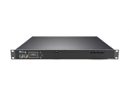 16 Group1x4(4x1) Fiber Optical Switch, SM, 1310/1550nm MPO16/APC 1U Chassis
 4-Optical 24-Electric Gigabit Management POE Switch FW4024GP
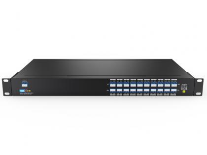 Single Fiber 20CH (40waves) DWDM MUX/ DEMUX, LC/UPC, 1U Rack
 Ethernet switch 24 PoE RJ45 Port and 6X10G SFP+ ES528X-PWR
 100G QSFP28 BIDI 1290nm/1310nm 20km Transceiver
 SFP 1.25G TX 1550 RX 1490 CWDM 180KM DDM Optical Transceiver
 Dual Fiber 8CH C29-C36 DWDM OADM, WEST TO EAST
 25G SFP28 DWDM Optical Transceiver

Address : Room 901, Building 6, JD Smart Industrial Park, No. 128, Juhua Stone Avenue, Huashan Town, Huadu District, Guangzhou City
Tel : +86 15989256178
Whatsapp : +86 15914235380
Email : sales@fiberwdm.com