48 Cores MPO to 48 LC/UPC
2*24 Cores MPO to 24 LC/UPC
12 Cores MPO to 12 LC/UPC
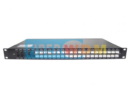
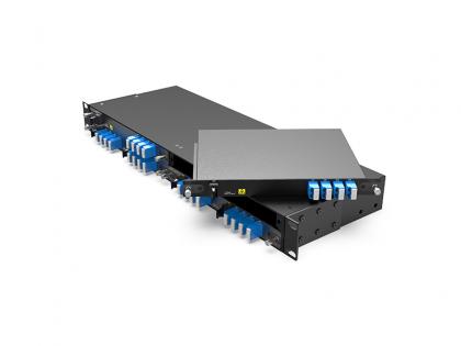
19 inch 2U Rack
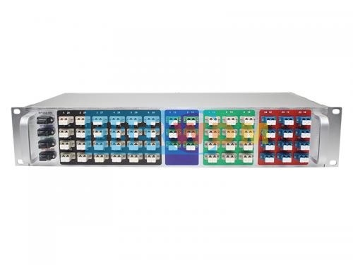
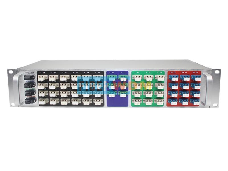
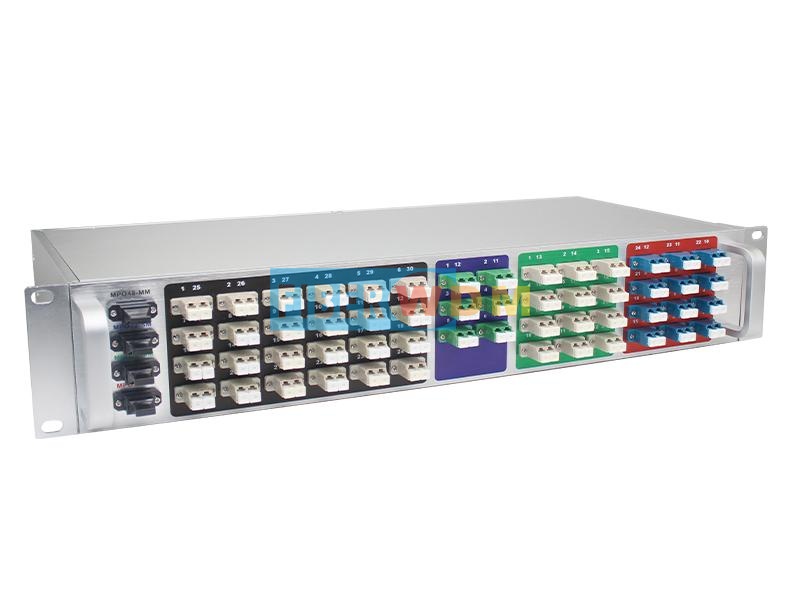
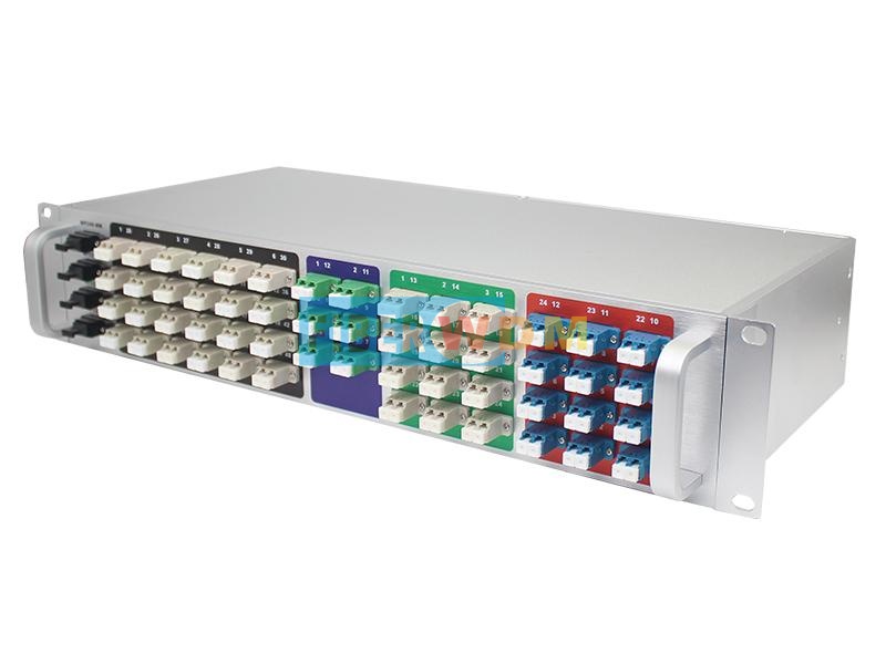
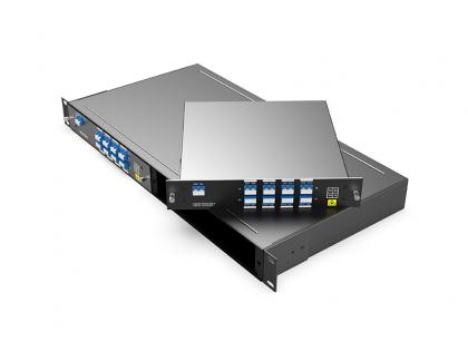
4 Channels MPO TO Dual LC Device 2U Rack
FIBERWDM Provide 4 Channels MPO to LC devices 2U Rack: one channels Multi-mode 48 cores MPO/UPC female to 48 LC/UPC connectors, and one Multi-mode 24 cores MPO/UPC female to 24 LC/UPC connectors, and one channels Single mode 24 cores MPO/UPC female to 24 LC/UPC connectors, and one channels Single mode 12 cores MPO/UPC female to 12 LC/APC in 2U Rack.
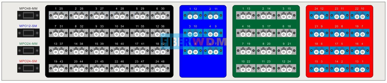
Product Panel
|
|
4 Channels MPO to LC devices 2U Rack
Product Specification
|
Parameter |
SM |
MM |
||
|
MPO/APC |
LC/UPC |
MPO/UPC |
LC/UPC |
|
|
IL(Insertion Loss) |
≤0.35dB |
≤0.15dB |
≤0.35dB |
≤0.15dB |
|
RL(Return Loss) |
≥45 dB |
≥50 dB |
≥25 dB |
≥35 dB |
|
Fiber Type |
SMF-28e |
OM4 |
||
|
Durability(dB) |
≤0.2dB (500 Matings,per EIA-455-21A) |
|||
|
Tensile Strength(dB) |
≤0.3dB (Max 66N) |
|||
|
Operation Temperature |
-20 ~+70℃ |
|||
|
StorageTemperature |
-40 ~+80℃ |
|||
|
Dimensions (HxWxD) |
440(L)x 88( H)x230(W)mm |
|||
Internal connection diagram
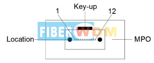
12 cores MPO female
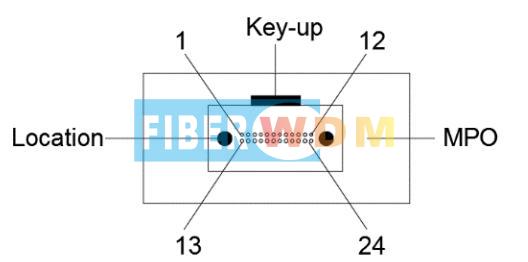
24 cores MPO female
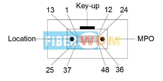
48 cores MPO female
|
|
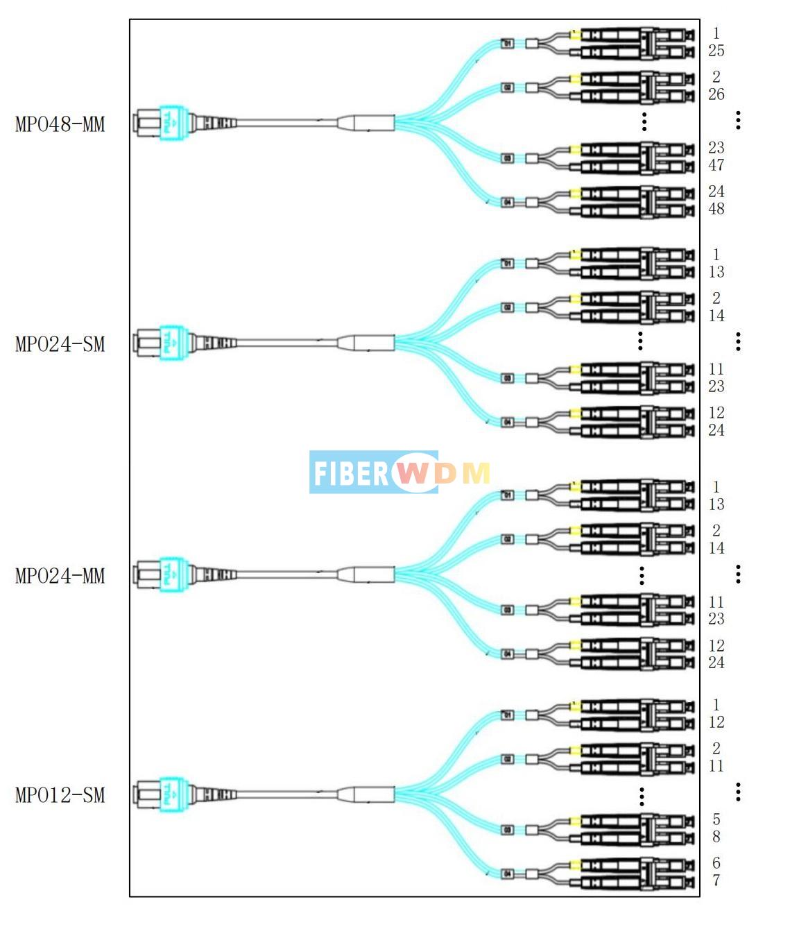
MPO TO LC/UPCconnection diagram
MPO To Dual LC
|
MPO Connector |
Dual LC Connector |
|
MPO48-MM Female
|
1-25 |
|
2-26 |
|
|
3-27 |
|
|
4-28 |
|
|
5-29 |
|
|
6-30 |
|
|
7-31 |
|
|
8-32 |
|
|
9-33 |
|
|
10-34 |
|
|
11-35 |
|
|
12-36 |
|
|
13-37 |
|
|
14-38 |
|
|
15-39 |
|
|
16-40 |
|
|
17-41 |
|
|
18-42 |
|
|
19-43 |
|
|
20-44 |
|
|
21-45 |
|
|
22-46 |
|
|
23-47 |
|
|
24-48 |
|
|
MPO24-MM Female
|
1-13 |
|
2-14 |
|
|
3-15 |
|
|
4-16 |
|
|
5-17 |
|
|
6-18 |
|
|
7-19 |
|
|
8-20 |
|
|
9-21 |
|
|
10-22 |
|
|
11-23 |
|
|
12-24 |
|
|
MPO24-SM Female |
1-13 |
|
2-14 |
|
|
3-15 |
|
|
4-16 |
|
|
5-17 |
|
|
6-18 |
|
|
7-19 |
|
|
8-20 |
|
|
9-21 |
|
|
10-22 |
|
|
11-23 |
|
|
12-24 |
|
|
MPO12-SM Female |
1-12 |
|
2-11 |
|
|
3-10 |
|
|
4-9 |
|
|
5-8 |
|
|
6-7 |
Related Tags :
Want to know about this product?
If you are interested in our products and want to know more details,please leave a message here,we will reply you as soon as we can.
 MTP/MPO Trunk Cable
 MPO TO Dual LC Device 10 X MPO TO 40 X Dual LC
 MPO TO LC optical breakout equipment
 100G QSFP28 CWDM4 10km LC Optical Transceiver
 Single Fiber 8CH (16Waves) O-BAND DWDM MUX DEMUX, LC/UPC, LGX Box, and 2 Slots 1U Rack
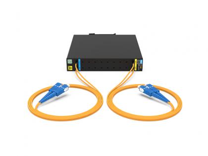 2x2 PLC SC/UPC 2.0MM 1.0M Fiber DIN Mounting Box 120*110*20MM
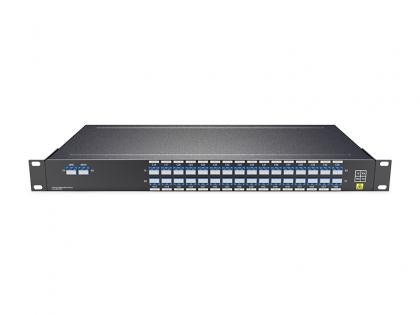 150GHz 32CH DWDM MUX DEMUX C14-H60(1566.31nm-1529.16nm )with Monitor Port,LC/UPC 1U Rack
 3G Video CWDM SFP Optical Transceiver support 1080P 60HZ Video

Address : Room 901, Building 6, JD Smart Industrial Park, No. 128, Juhua Stone Avenue, Huashan Town, Huadu District, Guangzhou City
Tel : +86 15989256178
Whatsapp : +86 15914235380
Email : sales@fiberwdm.com


