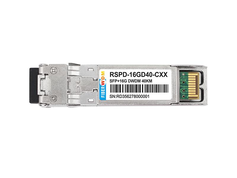
The SFP+ transceivers are high performance, cost effective modules supporting data rate of 16Gbps and 40km transmission distance with SMF.
The transceiver consists of three sections: a Cooled EML laser transmitter, a PIN photodiode integrated with a trans-impedance preamplifier (TIA) and MCU control unit. All modules satisfy class I laser safety requirements.
The transceivers are compatible with SFP Multi-Source Agreement and SFF-8472 digital diagnostics functions.
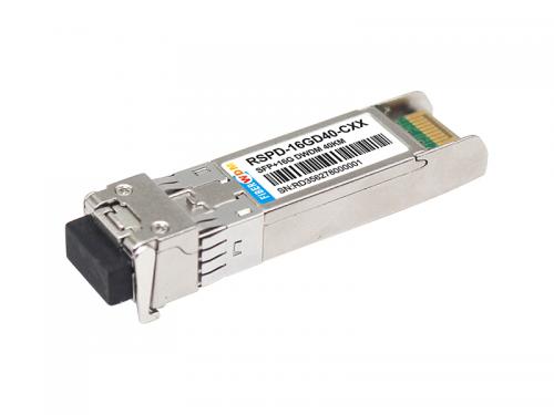
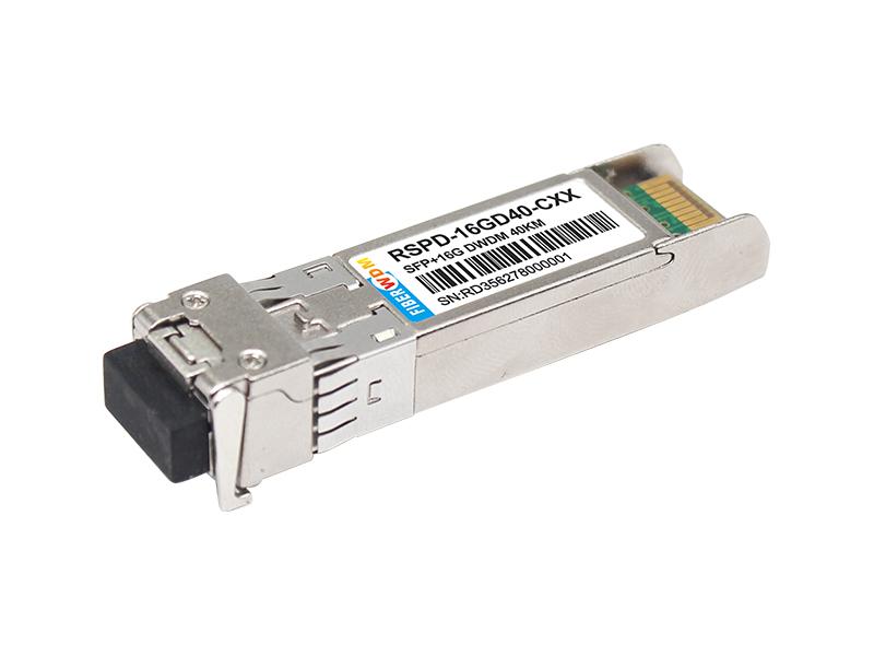
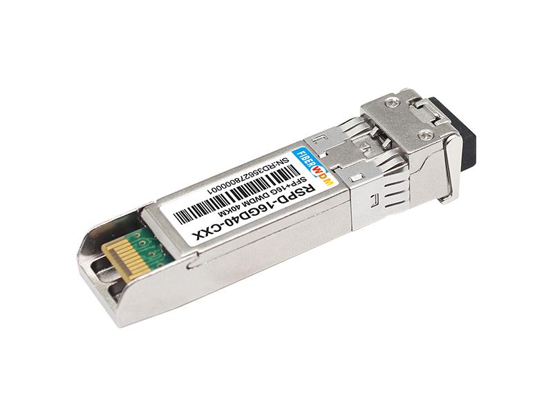
16Gbps FC DWDM SFP+ Transceiver, C-Band, EML, 40km Reach RSPD-16GD40-CXX
Product Features
Applications

Transceiver functional diagra
Absolute Maximum Ratings
| Parameter | Symbol | Min | Max | Unit |
| Supply Voltage | Vcc | -0.5 | 4.5 | V |
| Storage Temperature | Ts | -40 | +85 | °C |
| Operating Humidity | 5 | 85 | % |
Recommended Operating Conditions
| Parameter | Symbol | Min | Typical | Max | Unit |
| Operating Case Temperature | Tc | 0 | +70 | °C | |
| Power Supply Voltage | Vcc | 3.135 | 3.30 | 3.465 | V |
| Power Supply Current | Icc | 550 | mA | ||
| Data Rate | 4.25 | 16 | Gbps |
Optical and Electrical Characteristics

Notes:
1. The optical power is launched into SMF.
2. PECL input, internally AC-coupled and terminated.
3. Measured with a PRBS 231-1 test pattern @16000Mbps, BER ≤1×10-12.
4. Internally AC-coupled.
Timing and Electrical

iDagnostics

Digital Diagnostic Memory Map
The transceivers provide serial ID memory contents and diagnostic information about the present operating conditions by the 2-wire serial interface (SCL, SDA).
The diagnostic information with internal calibration or external calibration all are implemented, including received power monitoring, transmitted power monitoring, bias current monitoring, supply voltage monitoring and temperature monitoring.
The digital diagnostic memory map specific data field defines as following.

Pin Descriptions


Notes:
Plug Seq.: Pin engagement sequence during hot plugging.
1) TX Fault is an open collector output, which should be pulled up with a 4.7k~10kΩ resistor on the host board to a voltage between 2.0V and Vcc+0.3V. Logic 0 indicates normal operation; Logic 1 indicates a laser fault of some kind. In the low state, the output will be pulled to less than 0.8V.
2) Laser output disabled on TDIS >2.0V or open, enabled on TDIS <0.8V.
3) LOS is open collector output. Should be pulled up with 4.7k~10kΩ on host board to a voltage between 2.0V and 3.6V. Logic 0 indicates normal operation; logic 1 indicates loss of signal.
4) RD-/+: These are the differential receiver outputs. They are internally AC-coupled 100 differential lines which should be terminated with 100Ω (differential) at the user SERDES.
5) TD-/+: These are the differential transmitter inputs. They are internally AC-coupled, differential lines with 100Ω differential termination inside the module.
Recommended Interface Circuit

Mechanical Dimensions

Ordering information
RSPD-16GD40-CXX XX: 100GHZ ITU Grid Wavelength


Want to know about this product?
If you are interested in our products and want to know more details,please leave a message here,we will reply you as soon as we can.
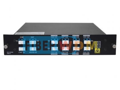
 SFP+ 16G C17-C61 DWDM 20KM DDM Optical Transceiver
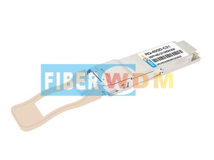
 40G QSFP+ LR4 10Km 1310nm LC Optical Transceiver
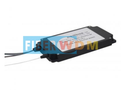
 Single Fiber 8CH(16 Waves) CWDM MUX DEMUX With Monitor Port
 100GHZ DWDM AAWG 40/48CH MODULE
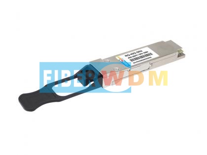
 Single Wave 40G DWDM QSFP+ PAM4 Dual LC Transceiver
 40Gs QSFP+ SR4 100m 850nm MPO Optical Transceiver
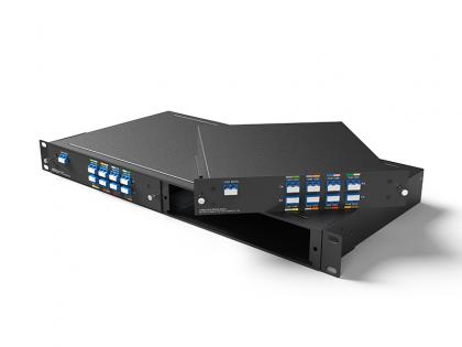
 Single Fiber 8CH DWDM MUX DEMUX With RB Filter, Plug-in LGX box, 2-slot 1U rack
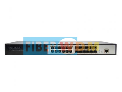 12-Optical 12-Electric Gigabit Management Switch FW5700-12G-12F

Address : Room 901, Building 6, JD Smart Industrial Park, No. 128, Juhua Stone Avenue, Huashan Town, Huadu District, Guangzhou City
Tel : +86 15989256178
Whatsapp : +86 15914235380
Email : sales@fiberwdm.com


