MEMS Variable Optical Attenuator VOA

MEMS Variable Optical Attenuator VOA

Product Features


  • Low insertion loss
  • Low polarization dependent
  • Compact size
  • Available in both normally open and normally closed states
  • Excellent reliability


Product Application


  • Power Management
  • Receiver protective
  • Channel Balance
  • Instrumentation


  • Product Detail

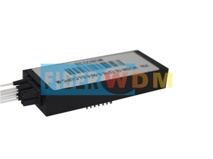
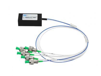
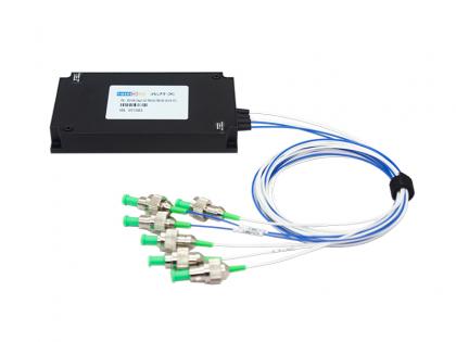
MEMS Variable Optical Attenuator (Mems VOAs)


Mirror MEMS attenuators (MEMS VOAs) are based on a micro-electro-mechanical system (MEMS) technology. The MEMS attenuators design achieves highly repeatable optical attenuation over C and/or L band through an electrically movable mirror on silicon.


Specifications


Parameters

Unit

Specifications

Wavelength Range

nm

850±40 / 1310±40

TestWavelength

nm

850 /1310

Attenuation Type


Bright / Dark

Insertion Loss 1, 2

dB

≤ 1.2

Attenuation Range3

dB

20/30/40

Attenuation Resolution

dB

Continuous

Return Loss

dB

≥ 30

TDL

dB

@0~10dB≤1.0

@10~20dB≤ 2.0

Repeatability 

dB

≤ 0.1

Operating Voltage

V

≤ 9

Durability

Cycles

≥ 109

Response Time

ms

≤ 5

Optical Power

mW

≤ 500

Operating Temperature

℃

-5~ +75

Storage Temperature

℃

-40 ~ +85

Relative Humidity

%

5 ~ 95

Dimension

mm

(Φ)5.5x(L)19±0.2

Note:   


  1. Room temperature,Excluding connectors, add 0.2dB one pair connectors.
  2.  For dark type, the voltage is 9V with 0dB attenuation.
  3. The voltage is 9v for the attenuation arrange.


MECHANICAL DRAWINGS

MEMS Variable Optical Attenuator (Mems VOAs)


MEMS Variable Optical Attenuator (Mems VOAs)


Ordering Information

FW-MM VOA-A-B-C-D-E-F

A

B

C

D

E

F

Attenuation w/o voltage

Fiber Type

TestWavelength

Tube Type

Fiber Length

Connector

BR:

Bright

DK:

Dark

M5:

MM, 50/125

M6:

MM, 62.5/125

X:

Others

850:

850nm

1310:

1310nm

X:

Others

25:

250um

90:

900um

X:

Others

05:

0.5m±5cm

10:

1.0m±5cm

X:

Others

OO:None

FP:FC/PC

FA:FC/APC

SP:SC/PC

SA:SC/APC

LP:LC/PC

LA:LC/APC

X:Others

Want to know about this product?

SEND A MESSAGE
Leave A Message

If you are interested in our products and want to know more details,please leave a message here,we will reply you as soon as we can.
Related Products
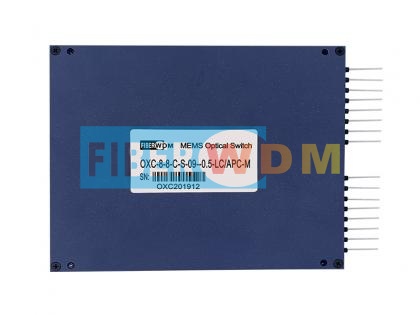
MEMS Fiber Optical Switch MXN MEMS Optical Switch
Features Proven MEMS durability and reliability Compact Form Factor TTL UART interface Qualified to Telcordia GR-1073-CORE and RoHS Applications Optical path selection AsAutomatic optical distribution rack
MEMS Fiber Optical Switch 1XN MEMS Optical Switch
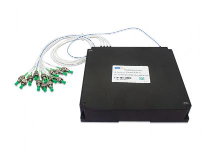
Features Proven MEMS durability and reliability Compact Form Factor Fast switching time Qualified to Telcordia GR-1073-CORE and RoHS Applications Opticalsignal switching androuting Optical network protection and restoration Optical path monitoring (Workingwith OTDR or OCM) Instrumentation resource sharing
1X12 MEMS Fiber Optical Switch,PM Fiber Module PM (Polarization-maintaining) 1X12 MEMS Fiber Optical Switch 1550nm 0.9MM 0.5M PM Fiber FC/APC 158x150x29nm Module
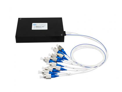
Features   Proven MEMS durability and reliability Compact Form Factor Fast switching time Qualified to Telcordia GR-1073-CORE and RoHS UART/TTL or UART/RS232 control interface
1X10 PM MEMS optical switch 1X10 PM MEMS optical switch
Features   Proven MEMS durability and reliability Compact Form Factor Fast switching time Qualified to Telcordia GR-1073-CORE and RoHS UART/TTL or UART/RS232 control interface
1X4 PM MEMS Optical Switch 1X4 PM MEMS Optical Switch
Features   Proven MEMS durability and reliability Compact Form Factor Fast switching time Qualified to Telcordia GR-1073-CORE and RoHS UART/TTL or UART/RS232 control interface
Dual 1x2 MEMS Switch(Module) Dual 1x2 MEMS Switch(Module)
RD-MS-Dual-1×2-PM-M-780-90-10-FA-TTL PM Dual 1×2 MEMS Optical Switch is a high-performance polarization-maintaining fiber optical switch based on Micro-Electro-Mechanical Systems (MEMS) technology. It is specifically designed for fiber optic communication and sensing applications requiring strict polarization state maintenance. Featuring an advanced micro-mirror drive architecture, it offers ultra-low insertion loss, high extinction ratio, fast switching speed, and exceptional reliability. It is widely used in fiber optic sensing systems, precision optical measurement, laser scanning microscopy, Fiber Bragg Grating (FBG) monitoring, polarization-sensitive optical path switching, and other demanding applications.
Passive Network Optical Taps 24* OTAPs Passive Network Optical Taps LC/UPC 1U Rack
Up to 24*OTAPs Optical Taps module, Support 24 lines traffic copy Low insertion loss – minimize impact on data flows Fully passive – monitoring infrastructure does not impact network availability Does not modify traffic – tools see real copies of the packets from the network Requires no power and does not have an IP address, providing safety from remote attacks Cost effective – avoid costly expenses managing SPAN ports  
32ch 150GHz DWDM MUX DEMUX 150GHz 32CH DWDM MUX DEMUX DUAL FIBER LC/UPC 1U Rack

150GHz C-band Flat top 32-Channel Athermal AWG, DWDM MUX DEMUX LC/UPC 1U RACK     Introduction   The 150GHz 32ch DWDM MUX DEMUX operate in C-band. And it meet the following specification over the operating temperature.   Definition Note:    All specifications should be guaranteed at the worst-case polarization state and over the entire operating environmental condition and end of life. The Insertion Loss of a device is defined as the maximum loss at a defined wavelength, taking into account the worst-case polarization state over the full operating temperature range. The Insertion Loss Uniformity of a device is the difference between the insertion loss of the best-case and worst-case channels. The Polarization Dependent Loss of a device is the maximum insertion loss difference between all polarization states at the defined wavelength. The Reference Passband is defined as a band of wavelengths around each center wavelength. It is used in the definition of crosstalk. The Adjacent Isolation of channel is the maximum insertion loss difference from the mean transmission at the ITU grid wavelength to the highest power over the all polarization and the ITU band of two adjacent channels. The Non-adjacent Isolation of channel is the maximum insertion loss difference from the mean transmission at the ITU grid wavelength to the highest power over the all polarization and the ITU band of the non-adjacent channels. The Total Crosstalk of channel is the total cumulative insertion loss difference from the mean transmission at the ITU grid wavelength to the highest power over the all polarization and the ITU band of all other channels including adjacent and non-adjacent channels. The Wavelength Accuracy is defined as the maximum difference between the defined wavelength and the center of measured 3dB passband.   Product Penal                           150GHz DWDM MUX DEMUX 32CH 1U Rack Technical Parameter   Parameter Specification Units Notes Min Type Max Channel Spacing 150 GHz   Nos of Channel 32 Ch   Channel Frequencies ITU Grid THz   Available Channel Frequency Range 191.2   196.7 THz   Channel Passband -60   +60 GHz   -0.48   +0.48 nm   Center Wavelength Accuracy -0.05   +0.05 nm   -6.25   +6.25 GHz   Insertion Loss     5.5 dB @Center Wavelength     6.0 dB Full Bandwidth Passband Ripple     0.6 nm Full Bandwidth Bandwidth @1.5dB 135     GHz   Bandwidth @3.0dB 160     GHz   Bandwidth @20dB     310 GHz   Insertion Loss Uniformity at ITU     1.50 dB   Polarization Dependent Loss     0.5 dB   Adjacent Channel Isolation 13 15   dB   Non-Adjacent Channel Isolation 30 35   dB   Total Cross Talk 11 13   dB   Directivity 50     dB   Return Loss with connectors 40 45   dB   Chromatic Dispersion -20   +20 ps/nm   PMD     0.5 ps   Optical Power Handling of Common Port     24 dBm     Operating Conditions   Parameter   Min Max Units Temperature   -5 70 ℃ Humidity Non-condensing 0 90 % R.H.   Storage Conditions   Parameter   Min Max Units Temperature   -40 85 ℃ Humidity Non-condensing 0 90 % R.H.   Channel Plan 32Port AWG - On grid   The AWG operate in C-band. The channels are as follows Table 1   Channel ITU Frequency Wavelength Channel ITU Frequency Wavelength No. Channel THz nm No. Channel THz nm 1   191.4000 1566.314 17   193.8000 1546.917 2   191.5500 1565.087 18   193.9500 1545.720 3   191.7000 1563.863 19   194.1000 1544.526 4   191.8500 1562.640 20   194.2500 1543.333 5   192.0000 1561.419 21   194.4000 1542.142 6   192.1500 1560.200 22   194.5500 1540.953 7   192.3000 1558.983 23   194.7000 1539.766 8   192.4500 1557.768 24   194.8500 1538.581 9   192.6000 1556.555 25   195.0000 1537.397 10   192.7500 1555.343 26   195.1500 1536.216 11   192.9000 1554.134 27   195.3000 1535.036 12   193.0500 1552.926 28   195.4500 1533.858 13   193.2000 1551.721 29   195.6000 1532.681 14   193.3500 1550.517 30   195.7500 1531.507 15   193.5000 1549.315 31   195.9000 1530.334 16   193.6500 1548.115 32   196.0500 1529.163   Table 2   Channel ITU Frequency Wavelength Channel ITU Frequency Wavelength No. Channel THz nm No. Channel THz nm 1   191.3625 1566.621 17   193.7625 1547.216 2   191.5125 1565.394 18   193.9125 1546.019 3   191.6625 1564.169 19   194.0625 1544.824 4   191.8125 1562.945 20   194.2125 1543.631 5   191.9625 1561.724 21   194.3625 1542...
Leave A Message
Leave A Message
If you are interested in our products and want to know more details,please leave a message here,we will reply you as soon as we can.

Home

Products

about

contact