

Features
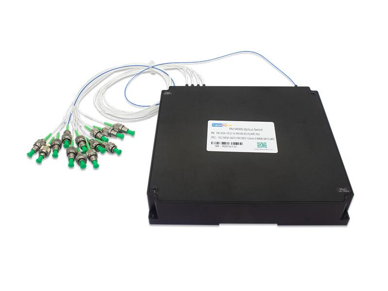
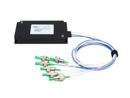
PM (Polarization-maintaining) 1X12 MEMS Fiber Optical Switch 1550nm 0.9MM 0.5M PM Fiber FC/APC 158x150x29nm Module
FW-MSX-1X12-15-PM-09-05-FC/APC-M3
MEMS 1xN optical switch is based on micro-electro-mechanical system technology. It allows channel selection between an input fiber and up to N output fibers by rotating the MEMS mirror.
The switch is bi-directional and can also be used as a Nx1 selector switch. The optical switch offers highly reliable, durable, long-life operation in a compact package.

Applications
Specifications
Table 1 Optical Specifications1
|
PARAMETER |
VALUE |
UNIT |
NOTE |
|
|
Wavelength |
15:1525~ 1568 |
nm |
Single-band: 13 or 15 or 16 Dual-band: 13&15 or 15&16 Full-band: 13&15&16 or 1290~ 1650 |
|
|
Test Wavelength |
1550 | nm | ||
|
MxN |
1x12 |
|||
|
Insertion Loss |
1x12 |
≤1.8 |
dB |
1. IL is measured at CWL, 23°C 2. IL is for Single-band. Dual-band adds 0.2dB 3. If with connectors, IL increases by 0.2~0.3dB 4. If at -5~65°C, IL increases by 0.4dB |
|
Return Loss |
≥45 |
dB |
Or customer specify |
|
|
Repeatability |
≤0. 1 |
dB |
Repeatability is defined after 100 cycles |
|
|
Crosstalk |
≥50 |
dB |
Or customer specify |
|
|
Polarization Dependent Loss |
≤0.35 |
dB |
||
|
Wavelength Dependent Loss |
≤0.6 |
dB |
WDL is measured at CWL±20nm, 23°C |
|
|
Temperature Dependent Loss |
≤0.6 |
dB |
|
|
|
Extinction Ratio |
≥18 |
dB |
Welding connectors of good quality |
|
|
Switch Time |
≤5 |
ms |
1.One set of connection configurations 2. Excluding protocol transmission time 3. When using optimized voltage ramp |
|
|
Durability |
≥1x10⁹ |
cycle |
|
|
|
Maximum Optical Power |
≤500 |
mW |
|
|
1. All specifications are without connectors.
Table 2 Electrical and Mechanical Specifications1
|
PARAMETER |
VALUE |
UNIT |
|
Latching Type |
Non-latching |
|
|
Control Type |
UART |
|
|
Supply Voltage |
5~ 12 |
V |
|
Power Consumption |
≤2, typical 1.7 |
W |
|
Connect Type |
||
|
Dimension |
158x150x29 |
mm |
1. All specifications belong to MSX M3.
Table 3 Environmental Conditions
|
PARAMETER |
VALUE |
UNIT |
|
Operation Temperature |
-5~65 |
℃ |
|
Storage Temperature |
-40~85 |
℃ |
|
Operation Humidity |
5~95 |
%RH |
|
Storage Humidity |
5~95 |
%RH |
Table 4 Pigtail and Connector Type/Length
|
PARAMETER |
VALUE |
UNIT |
NOTE |
|
Fiber Type |
|||
|
Fiber Pigtail (All Ports) |
250um fiber or 900um loose tube |
||
|
Fiber Length (All Ports) |
0.5±0.05 |
m |
Or customer specify |
|
Optical Connector (All port) |
FC/APC |
Or customer specify |
Mechanical Dimensions


Table 5 Electronic PIN Definition
|
Pin Number |
Name |
Input/Output |
Level |
Function |
| 1 |
NC |
No connect |
||
| 2 |
VCC |
Power supply |
+(5.0±5%) V Power Supply Max 150mA |
|
| 3 |
I/O |
LVTTL |
Reserved |
|
| 4 |
GND |
Power supply ground |
||
| 5 |
I/O |
LVTTL |
Reserved |
|
| 6 |
TXD |
Output |
LVTTL |
UART serial data output |
| 7 |
RXD |
Input |
LVTTL |
UART serial data input |
| 8 |
I/O |
LVTTL |
Reserved |
|
| 9 |
I/O |
LVTTL |
Reserved |
|
| 10 |
I/O |
LVTTL |
Reserved |
|
| 11 |
Case GND |
Case ground |
||
| 12 |
I/O |
LVTTL |
Reserved |
|
| 13 |
I/O |
LVTTL |
Reserved |
|
| 14 |
Reset |
Input |
LVTTL |
Reset, low active, the pulse width needs 4ms |
UART Control Setting
Baud Rate: 115200
Start Bits: 1
Data Bits: 8
Parity: None
Stop Bits: 1
Flow Control: None.
Communication Protocal
Protocol 1 (Default)
Command
|
FLAG |
LEN |
RES |
COMMA |
DATA |
SUM |
|
2 Byte |
1 Byte |
1 Byte |
1 Byte |
1 Byte |
FLAG: 0xEFEF or 0xAAAA
LEN: Total number of bytes from RES to SUM
RES: 0xFF
SUM: Checksum, SUM=FLAG+LEN+RES+COMMA+DATA
Response
|
FLAG |
LEN |
RES |
RESP |
DATA |
SUM |
|
2 Byte |
1 Byte |
1 Byte |
1 Byte |
1 Byte |
FLAG: 0xEDFA
LEN: Total number of bytes from RES to SUM
RES: 0xFF
SUM: Checksum, SUM=FLAG+LEN+RES+COMMA+DATA
Command List
|
Set Channel |
|||||||
|
Command |
FLAG1 |
LEN |
RES |
CMD |
Switch |
DATA |
SUM |
|
0xEFEF |
0x06 |
0xFF |
0x0D |
00/01 |
CHANNEL (1byte) |
SUM |
|
|
Eg:EF EF 06 FF 0D 00 00 01 F1 (set channel 1) EF EF 06 FF 0D 00 00 02 F2 (set channel 2) EF EF 06 FF 0D 00 00 03 F3 (set channel 3) |
|||||||
|
Response |
FLAG2 |
LEN |
RES |
RESP |
DATA |
SUM | |
|
0xEDFA |
0x04 |
RES |
0x04 |
Success:0xEE Fail:0xEF |
SUM |
||
|
eg: ED FA 04 FF 04 EE DC |
|||||||
|
Get Channel |
||||||
|
Command |
FLAG1 |
LEN |
RES |
COMMA |
DATA |
SUM |
|
0xEFEF |
0x03 |
RES |
0x02 |
SUM |
||
|
eg: EF EF 03 FF 02 E2 |
||||||
|
Response |
FLAG2 |
LEN |
RES |
RESP |
DATA |
SUM |
|
0xEDFA |
0x04 |
RES |
0x02 |
CHANNEL(1byte) |
SUM |
|
|
eg: ED FA 04 FF 02 07 F3 |
||||||
Note:When channel 0 is set, the voltage is 0, that is block state
Oder Information
|
Part No. |
Specification |
|
FW-MSX-1X12-15-PM-09-05-FC/APC-M3 |
PM (Polarization-maintaining) 1X12 MEMS Fiber Optical Switch 1550nm 0.9MM 0.5M PM Fiber FC/APC 158x150x29nm Module |
Want to know about this product?
If you are interested in our products and want to know more details,please leave a message here,we will reply you as soon as we can.
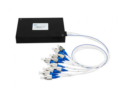
 MXN MEMS Optical Switch
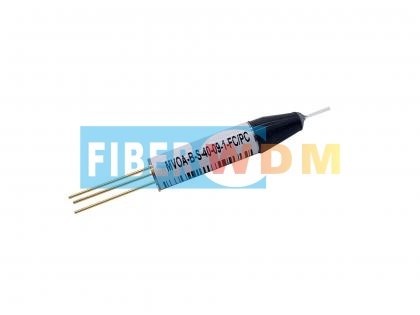 MEMS Variable Optical Attenuator VOA
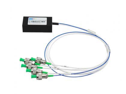
 1XN MEMS Optical Switch
 1X10 PM MEMS optical switch
 1X4 PM MEMS Optical Switch
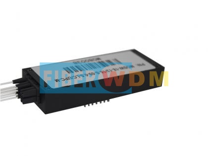
 Dual 1x2 MEMS Switch(Module)
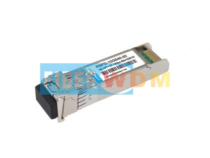 10G ER 40KM SFP+ Optical Transceiver
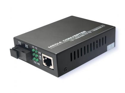 10/100M External Media Converter 1*RJ45 and 1*SFP Port Switch

Address : Room 901, Building 6, JD Smart Industrial Park, No. 128, Juhua Stone Avenue, Huashan Town, Huadu District, Guangzhou City
Tel : +86 15989256178
Whatsapp : +86 15914235380
Email : sales@fiberwdm.com


