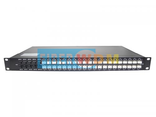
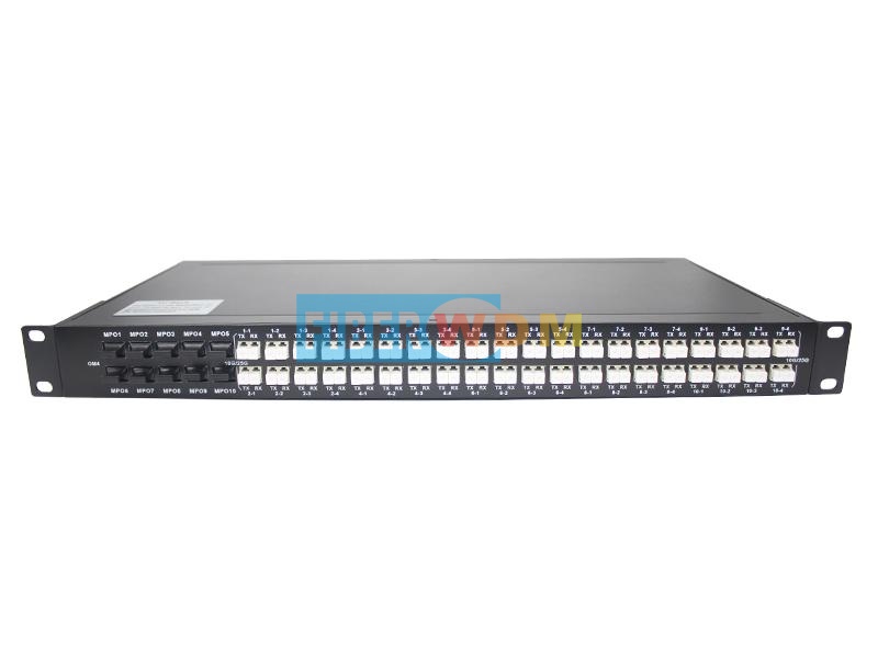
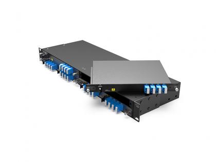
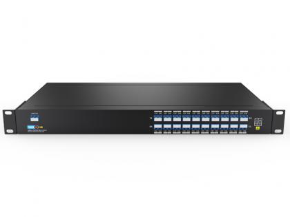
support 10 X 40G/ 100G MPO connectors to 40 X 10G/25G dual LC connectors
MPO TO Dual LC Device
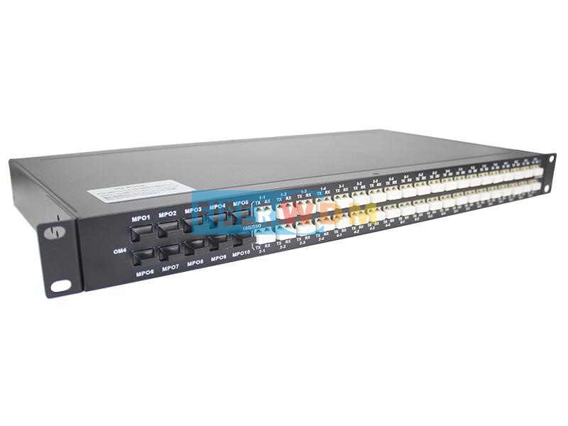
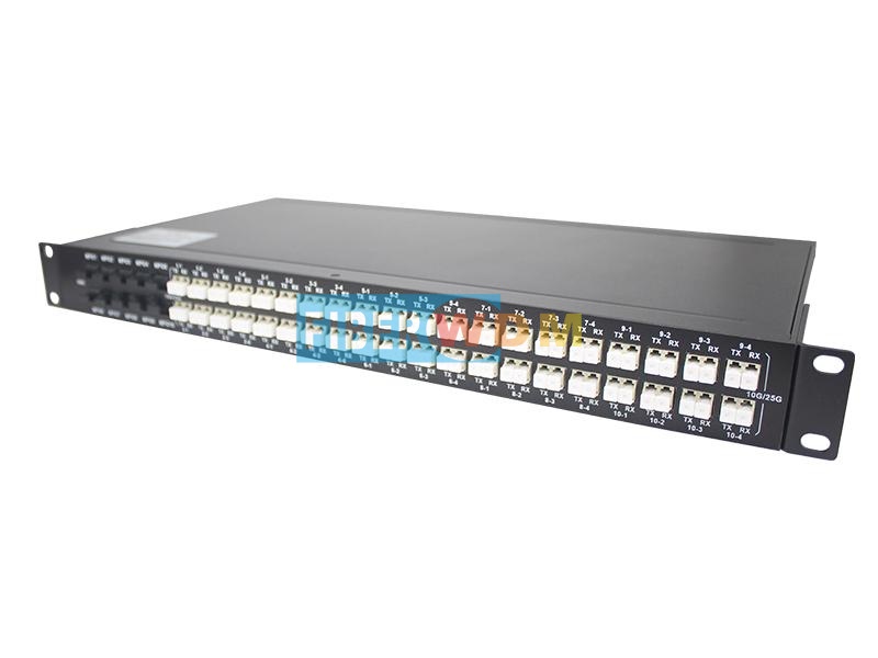
10 X MPO TO 40 X Dual LC 1U Rack
Fiberwdm provides MPO to dual LC device, can support 10 X 40G/ 100G MPO connectors to 40 X 10G/25G dual LC connectors. The device can be SM or MM, and 1U rack.
Product Specification
|
Parameter |
SM |
MM |
||
|
MPO/APC |
LC/UPC |
MPO/UPC |
LC/UPC |
|
|
IL(Insertion Loss) |
≤0.35dB |
≤0.15dB |
≤0.35dB |
≤0.15dB |
|
RL(Return Loss) |
≥45 dB |
≥50 dB |
≥25 dB |
≥35 dB |
|
Fiber Type |
SMF-28e |
OM4 |
||
|
Durability(dB) |
≤0.2dB (500 Matings,per EIA-455-21A) |
|||
|
Tensile Strength(dB) |
≤0.3dB (Max 66N) |
|||
|
Operation Temperature |
-20 ~+70℃ |
|||
|
StorageTemperature |
-40 ~+80℃ |
|||
|
Dimensions (HxWxD) |
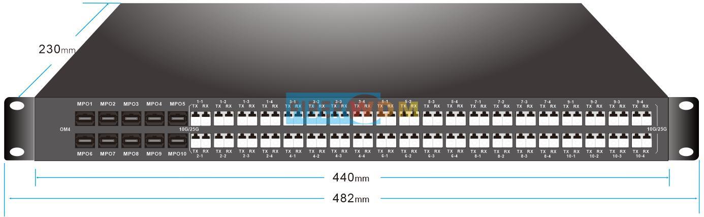
440(L)x 44( H)x230(W)mm |
|||
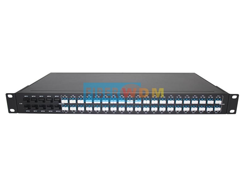
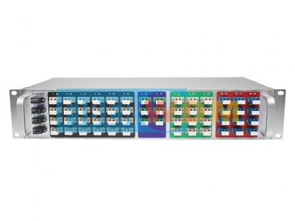
Product Panel
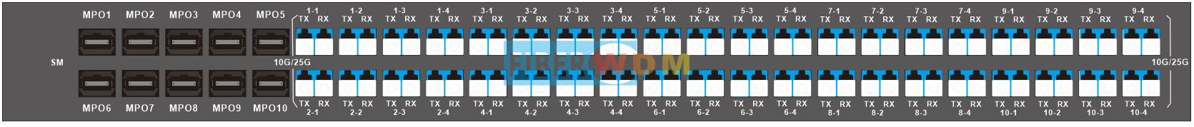
MPO TO Dual LC SM
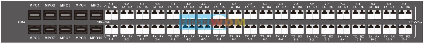
MPO TO Dual LC MM
Internal connection diagram
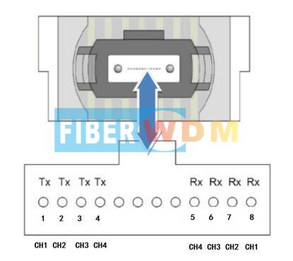
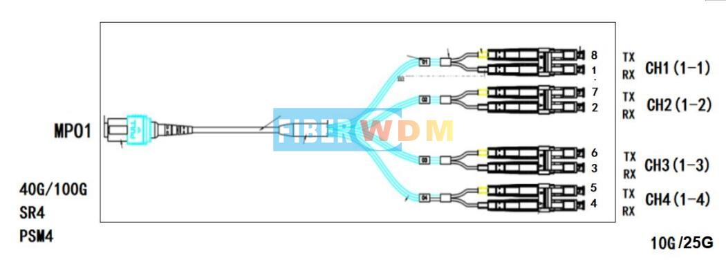
MPO To Dual LC
|
MPO Connector |
Dual LC Connector |
|
MPO1 |
1-1 |
|
1-2 |
|
|
1-3 |
|
|
1-4 |
|
|
MPO2 |
2-1 |
|
2-2 |
|
|
2-3 |
|
|
2-4 |
|
|
MPO3 |
3-1 |
|
3-2 |
|
|
3-3 |
|
|
3-4 |
|
|
MPO4 |
4-1 |
|
4-2 |
|
|
4-3 |
|
|
4-4 |
|
|
MPO5 |
5-1 |
|
5-2 |
|
|
5-3 |
|
|
5-4 |
|
|
MPO6 |
6-1 |
|
6-2 |
|
|
6-3 |
|
|
6-4 |
|
|
MPO7 |
7-1 |
|
7-2 |
|
|
7-3 |
|
|
7-4 |
|
|
MPO8 |
8-1 |
|
8-2 |
|
|
8-3 |
|
|
8-4 |
|
|
MPO9 |
9-1 |
|
9-2 |
|
|
9-3 |
|
|
9-4 |
|
|
MPO10 |
10-1 |
|
10-2 |
|
|
10-3 |
|
|
10-4 |
Package Information
MPO TO Dual LC 1U Rack
Order Information
|
Product No. |
Product description |
|
RD-10MPO12-40LC-SM |
MPO to dual LC device, 10 X 40G/ 100G MPO/UPC to 40 X 10G/25G dual LC/UPC, SM,1U Rack |
|
RD-10MPO12-40LC-MM |
MPO to dual LC device, 10 X 40G/ 100G MPO/UPC to 40 X 10G/25G dual LC/UPC, MM,1U Rack |
Related Tags :
Want to know about this product?
If you are interested in our products and want to know more details,please leave a message here,we will reply you as soon as we can.
 MTP/MPO Trunk Cable
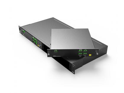
 4 Channels MPO TO Dual LC Device 2U Rack
 MPO TO LC optical breakout equipment
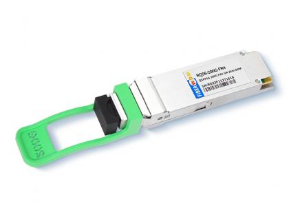 200G QSFP56 FR4 2KM LC PAM4 Optical Transceiver
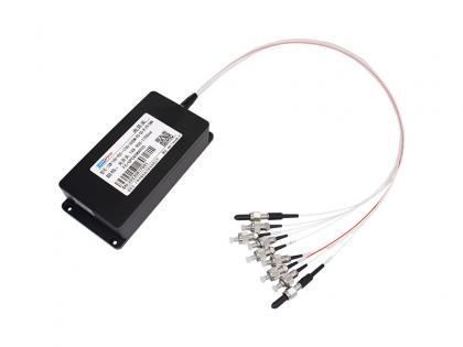
 FWDM 1X4 MUX G-PON 1310/1490 & XGS-PON 1270/1577 &1550/1610nm SC/APC LGX Box
 1X8 900-1700nm 300um Optical Switch
 Single Fiber 20CH (40waves) DWDM MUX/ DEMUX, LC/UPC, 1U Rack
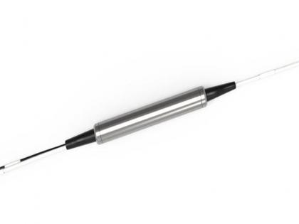 3 Port MM OM3 T31R85 WDM Component

Address : Room 901, Building 6, JD Smart Industrial Park, No. 128, Juhua Stone Avenue, Huashan Town, Huadu District, Guangzhou City
Tel : +86 15989256178
Whatsapp : +86 15914235380
Email : sales@fiberwdm.com


