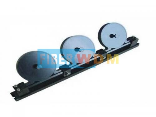
The mechanical three-ring polarization controller
The mechanical three-ring polarization controller is based on the principle of Birefringence produced by optical fiber under external force. The three rings are equivalent to λ/4, λ/2 and λ/4 wave plates, respectively. The light waves passing through λ/4 wave plates are converted into linearly polarized light, and the polarization direction is adjusted by/2 wave plates. Finally, the polarization state of linearly polarized light is changed into arbitrary polarization state by/4 wave plates. The delay effect produced by the birefringence effect is mainly determined by the cladding radius of the fiber, the fiber ring radius and the wavelength of the light, the adjusted polarization state can cover the entire poincare sphere.
Application area
Product structure diagram

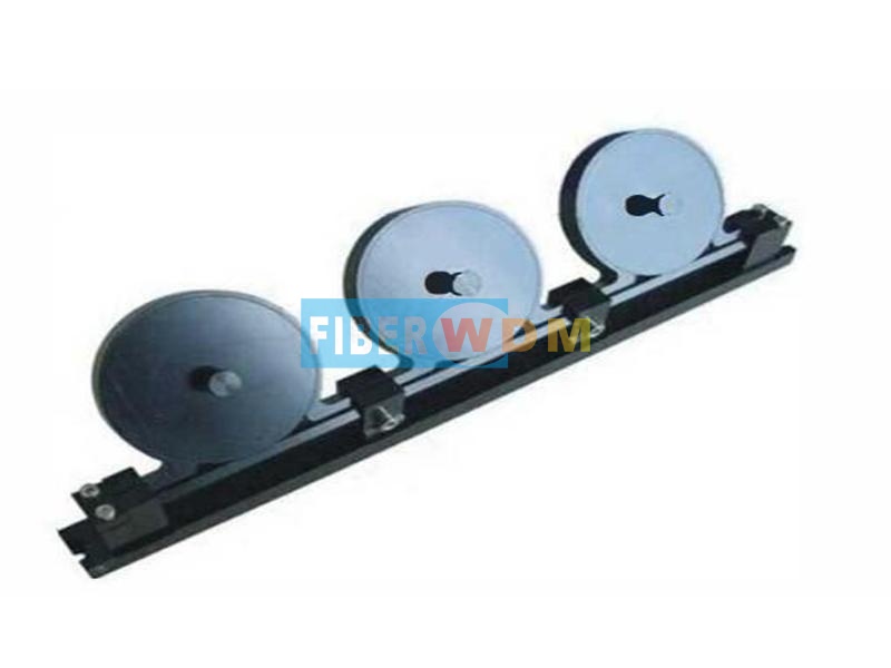
Schematic diagram of polarization controller

Relationship between single-loop delay and wavelength , number of loops in polarization controller.(Test unit: fiber loop diameter 40mm, fiber cladding diameter 900µm)
For example: Polarization controller fiebr loop fixed diameter of 40 mm, the cladding diameter of 900µm of tight-sheathed fiber around in the ghost.
When λ=1550nm , and loop number =1 , the ring is equivalent toλ/2 wave plate.
When λ=1550nm , and loop number =3, the ring is equivalent to 3λ/2 wave plate
Related Tags :
Want to know about this product?
If you are interested in our products and want to know more details,please leave a message here,we will reply you as soon as we can.
 High Precision Power Meter
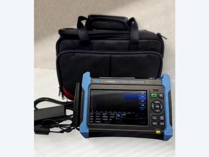 FW8422 Optical Time-Domain Reflectometer (OTDR)
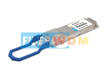 40G QSFP+ LR4 10Km 1310nm LC Optical Transceiver
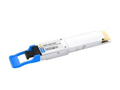 400G QSFP-DD EDR4 SM MPO12 2km Optical Transceiver
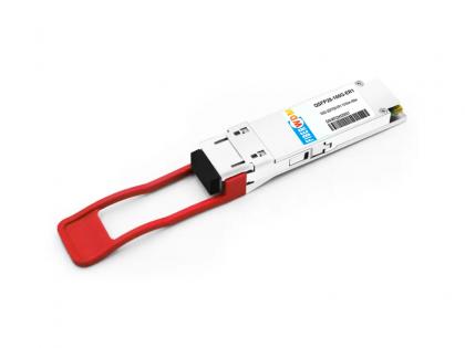 QSFP28-100G-ER1 100G QSFP28 ER1 Single Lambda 1310nm 40km PAM4 LC SMF DDM Transceiver Module
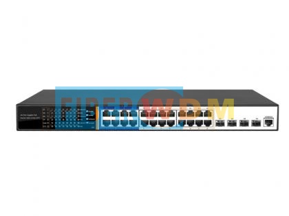 4-Optical 24-Electric Gigabit Management POE Switch FW4024GP
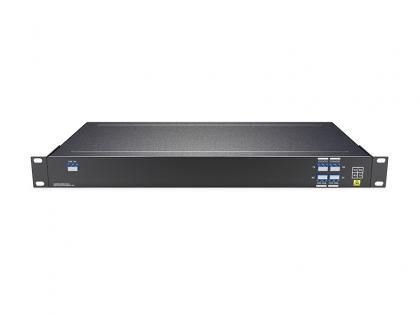 Single Fiber 4CH (8Waves) O-BAND DWDM MUX DEMUX, LC/UPC, 1U Rack
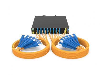 2x16 PLC SC/UPC 2.0MM 1.0M Fiber DIN Mounting Box 120*110*20MM

Address : Room 901, Building 6, JD Smart Industrial Park, No. 128, Juhua Stone Avenue, Huashan Town, Huadu District, Guangzhou City
Tel : +86 15989256178
Whatsapp : +86 15914235380
Email : sales@fiberwdm.com


