

Main Characteristics
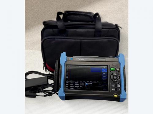
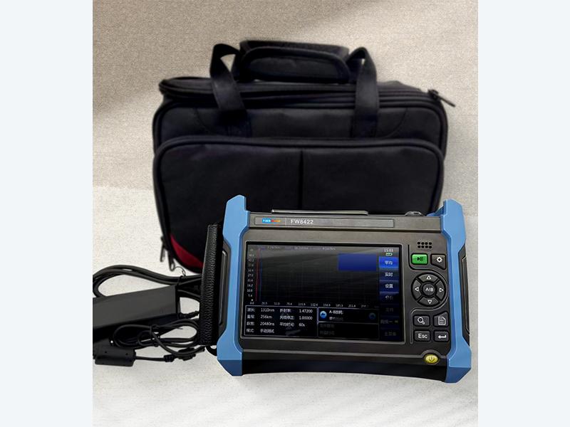
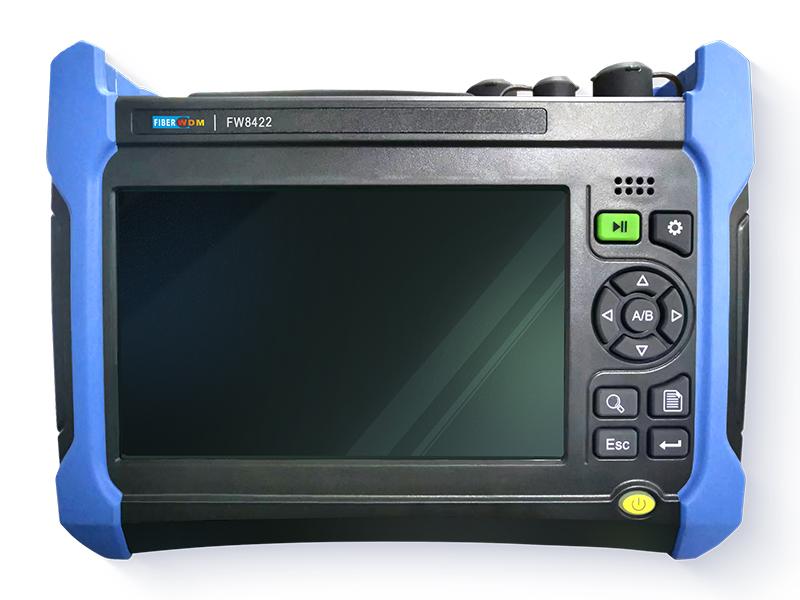
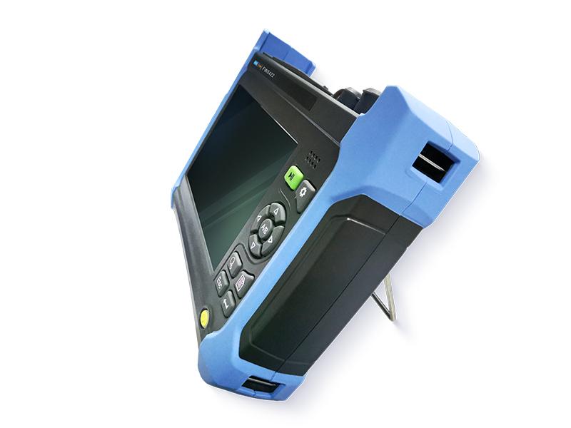
FW8422 Optical Time-Domain Reflectometer (OTDR)
Product Overview
FW8422 OTDR can used to test single-mode wavelengths of 1310nm, 1550nm, 1490nm, 1625nm and 1650nm, multi-mode wavelengths of 850nm and 1300nm as well as customized special wavelengths. It provides multiple optional modules, such as single wavelength, multi-wavelength and online test. With the maximum dynamic range of up to 50dB, the device can be used for remote multi-branch communication network test. It's designed with a minimum event dead zone of0.5mwhich makes the near connection easy to be supervised, and the lowest sampling resolution of2.5cmwhich enables it to locate the event point accurately. Additionally, the device is also designed with multiple convenient functional options, such as stable light source, optical power meter, visible red light source and fiber end face inspection tester.
FW8422 OTDR is designed with an operating temperature and a storage temperature of-10℃~50℃and-40℃~70℃respectively to meet both EMC requirements as well as vibration and shock test requirements, a MTBF(θ0) of 6000h or above to ensure a high reliability, and a 75W built-in Li battery to ensure an endurance for continuous measurement in the wild field.
Rapid automatic test
Due to the automatic test function of FW8422, it's not necessary for the user to know more about its operation. Connect the optical fiber and press the [Test] button. Then, the device will set the optimum test conditions automatically, and finally output accurate test results, such as the test curve and the list of events.
")
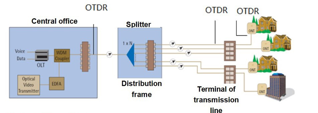
Unique PON network test
As an ideal tester of ODN and FTTx, FW8422 is provided a unique built-in PON network test function, can penetrate an optical splitter of up to 1:128, and can be used to test each branch of the PON network accurately.
Automatic monitoring and alarm of incoming optical signals
When the OTDR is testing the optical fiber line, the optical communication signal in the optical fiber, if any, will lead to inaccurate test results and even unrecoverable damages to the detectors in the device. FW8422 can monitor the optical communication signal in the optical fiber under test automatically. As long as the optical fiber under test is connected to the optical interface of FW8422, the device can automatically sense and monitor whether there is optical communication signal in it. Once an optical signal is monitored, it will prompt an alarm in time, so as to provide the quickest and the most timely protection for the device.
Typical Applications
Technical Specifications
|
Maximum dynamic range |
See the “Technical specifications for each standard module of FW8422 OTDR” for more information. |
|
Ranging accuracy |
± (0.75 + sample interval + 0.0025% × range) (excluding the refractivity placement error) (m) |
|
Ranging resolution |
0.05,0.1,0.2,0.5,1,2,4,8,16and32m |
|
Test range |
0.4,0.8,1.6,3.2,6.4,16,32,64,128, 256 and512km(singlemode); 0.4,0.8,1.6,3.2,6.4,16and32km(850nmmulti-mode) |
|
Testing PW |
3,5,10,30,80,160,320,640,1280,5120,10240and20480ns 3,5,10,30,80,160,320,640and1280ns (850nmmulti-mode) |
|
Maximum number of sampling points |
256k |
|
Linearity |
0.03dB/dB |
|
Loss resolution |
0.001dB |
|
Refractivity setting range |
1.00000~1.99999(step: 0.00001) |
|
Range unit |
km, m, thousand feet, feet |
|
Display |
800×480, 7-inch TFT color LCD (a capacitive touch screen in the standard configuration, and a resistive touch screen optional) |
|
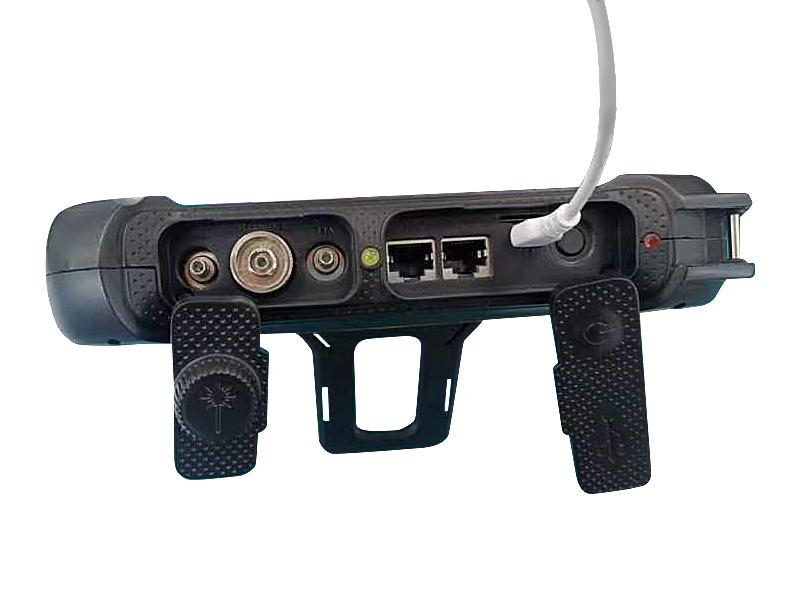
Optical output interface |
FC/UPC (standard configuration, with LC/UPC, SC/UPC and ST/UPC optional) |
|
Interface language |
Simplified Chinese, English, Russian and Korean available (contact the office for other language support) |
|
External interfaces |
USB, Micro-USB,10M/100MEthernet, earphone and MicroSD |
|
Power supply |
AC/DC adapter: AC100V~240V,50/60Hzand1.5A DC: 17V±3V(2A) Internal Li battery: 11.1V,6800mAh, battery operating time: 8h |
|
Maximum power consumption |
10W |
|
Dimensions |
252mm(W)×180mm(H)×55mm(D) |
|
Weight |
About1.8kg |
|
Environmental adaptability |
Operating temperature: -10℃~+50℃ (battery charging:5℃~40℃) Storage temperature: -40℃~+70℃ (battery: -20℃~60℃) RH: 5% ~95%, no condensation |
Technical specifications for each standard module of FW8422 OTDR1
|
Module number |
Operating wavelength |
Laser wavelength |
Dynamic range2(dB) |
Event dead zone3(m) |
ATT dead zone4(m) |
|
FW8422–1105 |
Single mode 1625nm(built-in filter) |
Single wavelength |
36 |
0.8 |
3 |
|
FW8422–1106 |
Single mode 1650nm(built-in filter) |
36 |
|||
|
FW8422–1201 |
Multi-mode 850nm |
24 |
1 |
5 |
|
|
FW8422–1202 |
Multi-mode 1300nm |
36 |
|||
|
FW8422–2101 |
Single mode 1310/1550nm |
Dual- wavelength |
37 / 35 |
0.5 |
3 |
|
FW8422–2102 |
Single mode1310/1550nm |
42 / 40 |
|||
|
FW8422–2103 |
Single mode1310/1550nm |
45 / 42 |
|||
|
FW8422–2105 |
Single mode1550/1625nm(built-in filter) |
36 / 36 |
|||
|
FW8422–2107 |
Single mode1550 /1650nm(built-in filter) |
36 / 36 |
|||
|
FW8422-2109 |
Single-mode1310 /1550nm |
46 / 46 |
|||
|
FW8422–2108 |
Single-mode1310/1550nm |
30 / 28 |
|||
|
FW8422–2201 |
Multi-mode850nm/1300nm |
26/34 |
0.7 |
5 |
|
|
FW8422–3101 |
Single-mode1310/1490/1550nm |
Three- wavelength |
37/35/35 |
0.5 |
3 |
|
FW8422–3102 |
Single-mode1310/1550/1625nm(built-in filter) |
37/35/35 |
|||
|
FW8422–3103 |
Single-mode1310/1550/1625nm(built-in filter) |
42/40/40 |
|||
|
FW8422–3104 |
Single-mode1310/1550 /1650nm(built-in filter) |
42/40/40 |
|||
|
FW8422–3105 |
Single-mode1310/1550/1650nm(built-in filter) |
37/35/35 |
|||
|
FW8422–3106 |
Single-mode1310/1550/1625nm(built-in filter) |
|
30/28/28 |
||
|
FW8422–4101 |
Single-mode1310/1490/1550/1625nm(built-in filter) |
Four- wavelength |
37/35/35/35 |
0.5 |
3 |
|
FW8422–4105 |
Single-mode1310/1490/1550/1650nm(built-in filter) |
37/35/35/35 |
|||
|
FW8422-4001 |
Single-mode1310/1550nm, multi-mode 850/1300nm |
37/35/26/34 |
0.7 |
5 |
|
|
FW8422-4002 |
Single-mode1310/1550nm, multi-mode 850/1300nm |
|
30/28/24/28 |
0.7 |
5 |
Notes: 1. One must and only one can be chosen for the standard module.
2. An ambient temperature of23℃±5℃, the maximum test PW, over 500 times averagely, and a SNR of 1.
3. A range of1.6kmor smaller, a PW of 3ns, a fiber end face reflection loss of 40dB or above, and a typical value.
4. A range of1.6kmor smaller, a PW of 5ns or smaller, a fiber end face reflection loss of 50dB or above, and a typical value.
Order Information
Main unit: FW8422 OTDR
Standard configuration:
|
S/N |
Description |
Remarks |
|
1 |
Power line assembly |
Power line and power adapter: an input voltage of 100~240V, 50~60Hz, an output voltage and an output current of 19V and3.42Arespectively at2.0A |
|
2 |
User manual |
- |
|
3 |
Product certificate of conformity |
- |
|
4 |
CD |
Including simulation analysis software |
|
5 |
Special portable soft bag of OTDR |
- |
|
6 |
Special strap of OTDR |
- |
Options:
|
No. |
Description |
Function |
|
FW8422-001 |
USB |
USB |
|
FW8422-002 |
SD card |
SD card |
|
FW8422-003 |
USB data cable |
USB data cable |
|
FW8422-004 |
Spare battery pack |
6417LB-1192 |
|
FW8422-005 |
LC, SC and ST adapters |
LC, SC and ST adaption |
|
FW8422-006 |
Single-mode optical fiber adaption jumper |
FC/UPC adapted to FC/APC |
|
FW8422-007 |
Single-mode optical fiber adaption jumper |
FC/UPC adapted to SC/UPC |
|
FW8422-008 |
Single-mode optical fiber adaption jumper |
FC/UPC adapted to LC/UPC |
|
FW8422-009 |
Special engineering plastic case of OTDR |
Special engineering plastic case (including the strap) |
Related Tags :
Want to know about this product?
If you are interested in our products and want to know more details,please leave a message here,we will reply you as soon as we can.
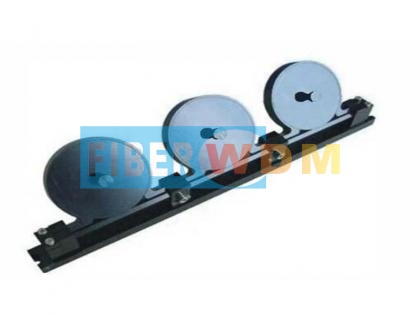 Three-ring Polarization Controller
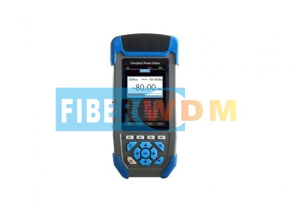 High Precision Power Meter
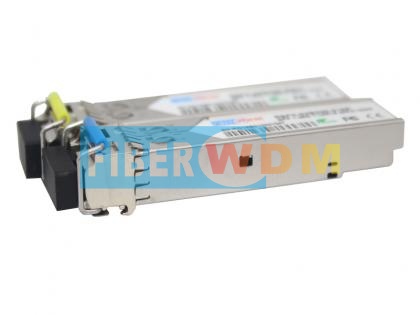 3G Video CWDM SFP Optical Transceiver support 1080P 60HZ Video
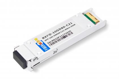 XFP 10G DWDM 80km Transceiver
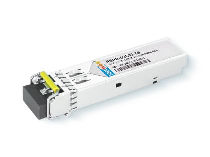 1.25G SFP CWDM 80km Optical Transceiver
 100Channel 1×2 Optical Switch
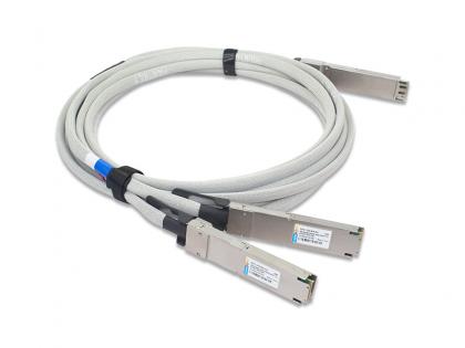 Hairtail+ 800G IB NDR OSFP Breakout to 2xOSFP Direct Attached Cable
 8 OTAPs Passive Network Optical Taps Module

Address : Room 901, Building 6, JD Smart Industrial Park, No. 128, Juhua Stone Avenue, Huashan Town, Huadu District, Guangzhou City
Tel : +86 15989256178
Whatsapp : +86 15914235380
Email : sales@fiberwdm.com


