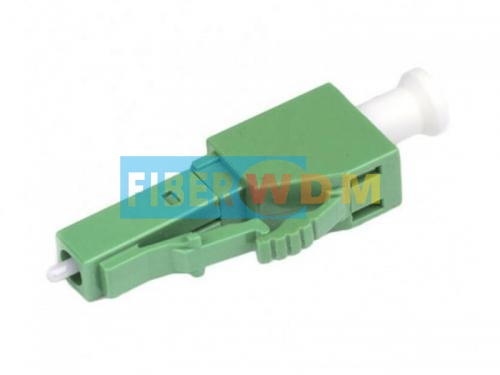
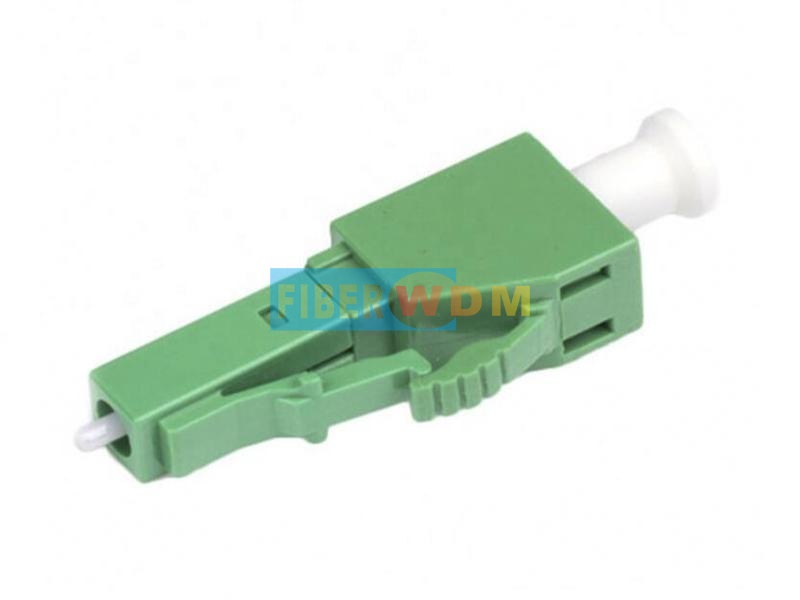
1650nm FBG Reflector LC/APC
The fiber brag grating reflector(FBG Reflector) is a low-cost specific band reflector mounted on the optical network unit (ONU) side. It can reflect light pulses (1650 +/- 5 nm) from the OTDR on the fiber line terminal (OLT) side nearly 100%, while the working bands of the passive optical network (PON) are transmitted normally. The OTDR can determine whether the fiber line is normal by detecting the signal reflected by the fiber grating reflector. When the reflected signal is lower than the normal value, the line loss is too large; when the reflection value is 0, the optical fiber line is broken。Therefore, we can maintain the fiber line in time by the real-time monitoring of the fiber line.
Application
Detection and maintenance of Passive Optical Network lines (applied to FTTx).

Optical parameter
|
item |
parameter |
specification |
unit |
Remarks |
|
|
1 |
wavelength range |
Pass band |
1260~1625 |
nm |
- |
|
Reflect band |
1644.5~1655.5 |
nm |
- |
||
|
2 |
Pass band |
IL |
≤1.4 |
dB |
@1260~1360 |
|
≤1.4 |
dB |
@1460~1600 |
|||
|
≤3.4 |
dB |
@1600~1625 |
|||
|
ORL |
>35 |
dB |
@1260~1580 |
||
|
>30 |
dB |
@1580~1620 |
|||
|
>20 |
dB |
@1620~1625 |
|||
|
3 |
Reflect band |
IL |
>21 |
dB |
@1644.5~1655.5 |
|
ORL |
≤1.0 |
dB |
@1644.5~1655.5 |
||
|
4 |
PDL |
≤0.4 |
dB |
@1260~1600 |
|
|
5 |
Ripple |
≤0.6 |
dB |
@1644.5~1655.5 |
|
|
6 |
TDL |
≤0.5 |
dB |
@1260~1600 |
|
|
7 |
Max Optical Power Handling |
27 |
dBm |
- |
|
|
8 |
Plug Times |
>500 |
Times |
- |
|
|
9 |
Connector |
LC/APC |
- |
- |
|
Structure
The FBG reflector adopts a standard LC connector structure, and its external dimensions are as follows:

Working/storage conditions
|
parameter |
specification |
unit |
|
Working temperature |
-25 ~ +65 |
°C |
|
Working humidity |
5~95 |
%RH |
|
Storage temperature |
-40 ~ +85 |
°C |
|
Storage humidity |
5~95 |
%RH |
Related Tags :
Want to know about this product?
If you are interested in our products and want to know more details,please leave a message here,we will reply you as soon as we can.
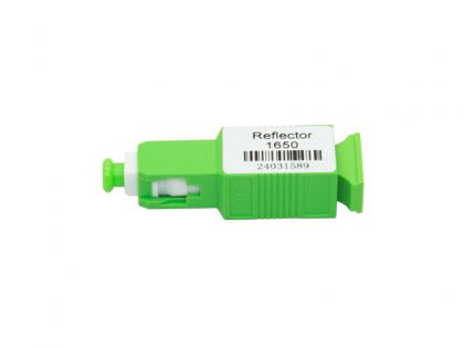 1650nm FBG Reflector SC/APC
 QSFP28-100G-ER1 100G QSFP28 ER1 Single Lambda 1310nm 40km PAM4 LC SMF DDM Transceiver Module
 10G SFP+ Converter
 Splitter PLC 1X64 LC/APC 1U Rack 440*200*44mm
 3 Port CWDM filter CWDM ITU Component
 10G Media Converter
 2.5G SFP CWDM 80km Optical Transceiver
 10G Multimode 850nm Industrial-grade 10Pin Optical Module

Address : Room 901, Building 6, JD Smart Industrial Park, No. 128, Juhua Stone Avenue, Huashan Town, Huadu District, Guangzhou City
Tel : +86 15989256178
Whatsapp : +86 15914235380
Email : sales@fiberwdm.com


