

Feature Description
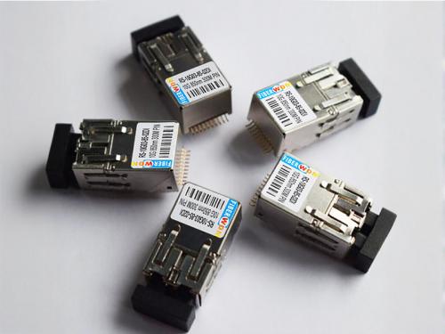
10G Multimode 850nm Industrial-grade 10Pin Optical Module
RS-10G03-85-02DI
|
Feature Description
|
Applications
|
Description
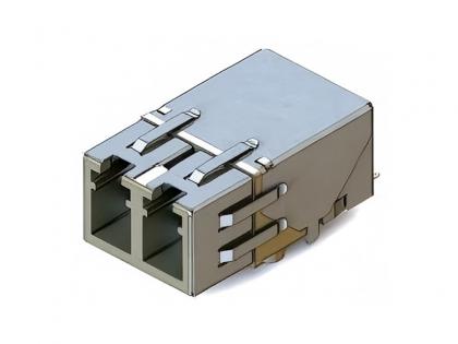
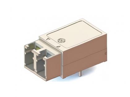
The RS-10G03-85-02DI dual-fiber bidirectional ultra-compact optical transceiver module integrates the transmitting and receiving components within a compact metal housing, significantly enhancing its electromagnetic interference resistance.
The optical transmitter section employs a high-power LD, with the transmit signal pins (TD+ and TD-) adhering to the CML interface standard.
The optical receiver section consists of a PIN photodiode, a preamplifier with transimpedance, and a limiting amplifier, with the receive signal pins (RD+ and RD-) also conforming to the CML interface standard.
The signal detection pin (SD) follows the standard LVTTL interface level. The module can enter a power-saving mode via the transmit disable pin (TDIS).
The module's pin configuration and mounting dimensions are fully compatible with similar products from STRATOS. Functional pins, mounting, and form factors can be customized according to user requirements, ensuring flexible application.
Rigorous screening and environmental testing guarantee the module's reliability and adaptability, featuring resistance to vibration, electromagnetic interference, humidity, and extreme temperatures. It is widely suitable for medical, power, high-altitude, and other demanding environments.
With its compact size, lightweight, and all-metal construction, the module stands at a mere 12mm in height, facilitating easy installation in space-constrained boards or chassis.
Module Principle Block Diagram

Module Parameter
|
Absolute Maximum Ratings |
|||||
|
Parameter |
Symbol |
minimum value |
Typical value |
maximal value |
unit |
|
Storage temperature |
TSTG |
-55 | - | +85 | ℃ |
|
Soldering temperature |
TSOLD |
- | - |
+260 |
℃ |
|
Soldering time |
tSOLD |
- | - | 5 | S |
|
Power supply voltage |
VCC |
+3 |
- |
+3.6 |
V |
|
Data input voltage |
VI |
-0.5 |
- |
VCC |
V |
|
Differential input voltage (peak-to-peak) |
VD |
- | - |
2.0 |
V |
|
Note: 1. The module cannot pass through the reflow soldering machine; 2. After pin soldering, cleaning cannot be done by spraying—only wiping is permitted. |
|||||
|
Recommended Working Conditions |
|||||
| Parameter | Symbol | minimum value | Typical value | maximal value | unit |
|
Working temperature |
TA |
-40 |
|
+85 |
℃ |
|
Power supply voltage |
VCC |
+3.3 |
V | ||
|
Transmit differential input voltage (peak-to-peak) |
VD |
0.2 |
1 | V | |
|
Send cutoff voltage |
VTD |
2.0 |
V | ||
|
Enable voltage transmission |
VTEN |
0.8 |
V |
||
|
Signal receiving terminal matching |
RL |
50 |
Ohms |
||
Data input/output port details


Module Performance
|
Transmission Section Test Conditions: VCCTX=3.3V, TA=25°C, Test Module Rate=10.3125Gbps, PRBS31 |
|||||
|
Parameter |
Symbol |
minimum value |
Typical value |
maximal value |
unit |
|
Data rate |
Bitrate |
- |
10.3125Gbps |
- | - |
|
Output optical power |
PO |
-5 | - | +1 |
dBm |
|
Output optical wavelength |
λOUT |
840 | 850 | 860 |
nm |
|
Extinction ratio |
ER |
3 | 5 | - |
dB |
|
Input current |
ICC |
- | 120 | 160 |
mA |
|
Rise/Fall Time of Optical Signal (20% to 80%) |
tRF |
- | - | 0.1 |
ns |
|
Shake |
Tj |
- | - | 80 | ps |
|
Send shutdown voltage |
VD |
2.0 | - |
VCC |
V |
|
Enable voltage transmission |
VEN |
- | - | 0.8 | V |
|
Reception section Test conditions: VCCRX=3.3V, TA=25℃, test module rate=10.3125Gbps, PRBS31 |
|||||
|
Parameter |
Symbol |
minimum value |
Typical value |
maximal value |
unit |
|
Receiving sensitivity |
S | - | - | -10 |
dBm |
|
Shake |
Tj |
- | - | 80 |
ps |
|
Rise/Fall Time of Optical Signal (20% to 80%) |
tR,F |
- | - | 100 |
ps |
|
Optical modulation amplitude |
OMA |
30 | - | - |
μW |
|
Optical input wavelength range |
λIN |
840 | - | 860 |
nm |
|
Optical return loss |
ORL |
12 | - | - |
dB |
|
Input current |
ICC |
- | 70 | 120 |
mA |
|
Signal detection arbitration time |
tSDAS |
- |
<10 |
50 |
μs |
|
Signal detection timeout period |
TSDDA |
- |
<10 |
50 |
μs |
|
Signal detection failure arbitration level |
SDOFF |
-21 | - | - |
dBm |
|
Signal detection arbitration level |
SDON |
- | - | -19 |
dBm |
|
Signal detection lag |
HYS |
2 | - | 4 |
dB |
|
Receive data output low level |
VOL-VCC |
-1.810 |
- |
-1.475 |
V |
|
Receive data output high level |
VOH-VCC |
-1.165 |
- |
-0.880 |
V |
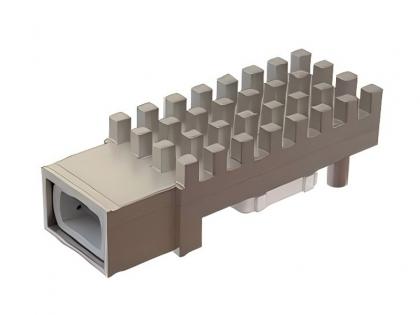
Pin Definition
Side view

|
PIN |
Symbol |
Type |
Description |
| 1 |
TD+ |
CML,Input |
Input data to the forward terminal |
| 2 |
GND |
Supply |
Ground |
| 3 |
TD- |
CML,Input |
Reverse end input for sending data |
| 4 |
VCCTX |
Supply |
Power source |
| 5 |
LOS |
LVTTL,Output |
Signal loss output |
| 6 |
TxDIS |
LVTTL,Input |
Send shutdown signal input |
| 7 |
RD+ |
CML,Output |
Positive terminal output of received data |
| 8 |
SDA |
LVTTL,I/O |
IIC communication port |
| 9 |
RD- |
CML,Output |
Reverse terminal output of received data |
| 10 |
SCL |
LVTTL,I/O |
IIC communication port |
Note: 2. If the TX_DISABLE function is used, the TDIS pin should be pulled up to the power supply to maintain a high level on this pin; if the TX_DISABLE function is not used, the TDIS pin should be pulled down to ground to maintain a low level on this pin and must not be left floating, otherwise it may cause abnormal module operation.
Dimension Drawing(mm)

Module Installation Diagram (Top View) (mm)

PCB Mounting Dimension Drawing (No wiring allowed in the hatched areas shown in the figure)
Module Installation Diagram


Module Installation Diagram

The specifications and quantities of screws, washers, and spring washers selected for module installation can be found in the Module Screw Installation Table.
Example: If the PCB thickness is 2.0mm, then select 1 round head M2x4mm screw + 1 φ2 washer + 1 φ2 spring washer per mounting hole.
If the PCB thickness is 1.6mm, then select 1 round head M2x3mm screw + 1 φ2 washer + 1 φ2 spring washer per mounting hole.
|
Module Screw Installation Table |
|||||||
|
No. |
PCB board thickness |
Screw |
Washer |
Spring washer |
|||
|
specifications |
Qty |
specifications |
Qty |
specifications |
Qty | ||
| 1 |
1.6 |
Round head M2×3mm |
1 |
φ2 |
1 |
φ2 |
1 |
| 2 | 2.0 |
Round head M2×4mm |
1 |
φ2 |
1 |
φ2 |
1 |
| 3 | 2.2 |
Round head M2×4mm |
1 |
φ2 |
1 |
φ2 |
1 |
| 4 | 2.5 |
Round head M2×4mm |
1 |
φ2 |
1 |
φ2 |
1 |
Ordering information
|
Part Number |
Product Description |
|
RS-10G03-85-02DI |
Dual fiber 10G Multimode 850nm 300m Industrial-grade 10Pin Mini Optical Transceiver Module |
Want to know about this product?
If you are interested in our products and want to know more details,please leave a message here,we will reply you as soon as we can.
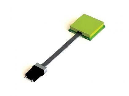
 10PIN Miniature Single-Channel Optical Module
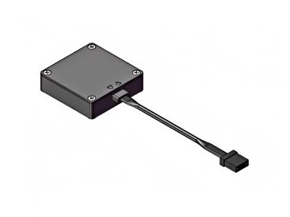
 12PIN Mini Single-Channel Optical Module
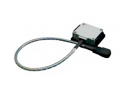
 SNAP12 Series Parallel Optical Transceiver Module
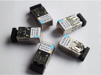
 LCC Series Parallel Optical Transceiver Module
 POB Series Single-Mode 4-Channel Parallel Optical Transceiver Module
 POB24 Series Parallel Optical Transceiver Module
 POB48 Series Parallel Optical Transceiver Module
 10G 1310nm 10KM Dual-Fiber Industrial-Grade 10PIN Surface-Mount Miniaturized Optical Transceiver

Address : Room 901, Building 6, JD Smart Industrial Park, No. 128, Juhua Stone Avenue, Huashan Town, Huadu District, Guangzhou City
Tel : +86 15989256178
Whatsapp : +86 15914235380
Email : sales@fiberwdm.com


