
Product Features
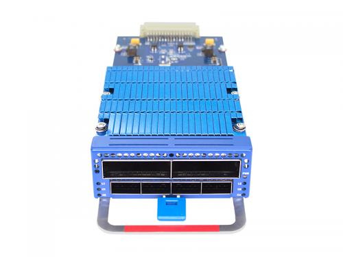
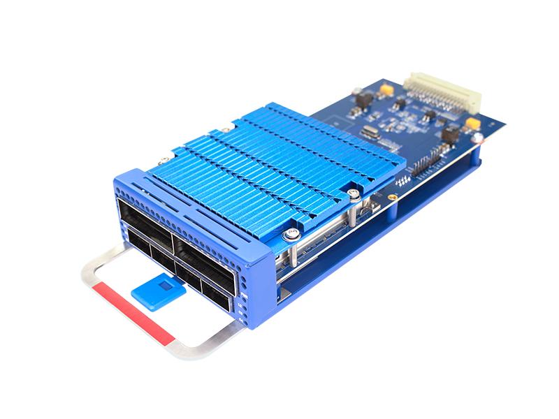
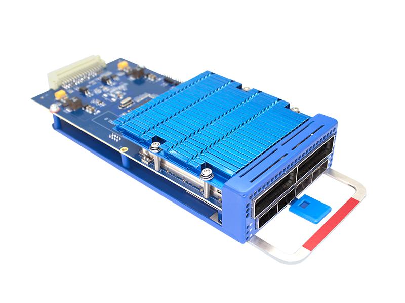
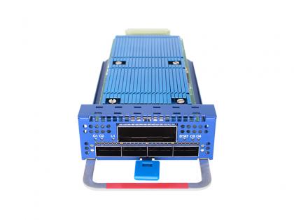
2*100G QSFP28 to 200G CFP2 TMUX board FW842
2*100G QSFP28 to 200G CFP2 TMUX card is designed for fiber optic links and provides 200G service access. It can convert two channels of 2*QSFP28 100G to CFP2 200G. The CFP2 coherent optical module has adjustable wavelengths and can be used in conjunction with DWDM multiplexers/demultiplexers to achieve wavelength division multiplexing transmission. This solution offers a high-quality resolution for addressing the challenges of limited fiber resources and high fiber line losses.
Product parameters
|
Parameters |
Describe |
|
|
Maximum capacity of single board |
2*100G dual-directional transmission 2*100G unidirectional transmission |
|
|
Wavelength (frequency) range |
DWDM:1529.16mm-1567.14nm(191.3THz-196.05THz) |
|
|
Adjustment method |
DP-QPSK@100G; DP-16QAM@200G; DP-8QAM@200G; DP-QPSK@200G; DP-8QAM@300G: DP-16QAM@400G |
|
|
Line side protocol |
Open ROADM/Open ZR+/SCFEC |
|
|
Dispersion tolerance |
±40000ps/nm@100G |
|
|
OSNR Tolerance |
<11.5dB@100G DP-QPSK:<18.5dB@200G DP-8QAM;<21.5dB@200G DP 16QAM;<14dB@200G DP-QPSK; |
|
|
Service access type |
100GE,100GE KR4,OTU4 and 100G FlexE |
|
|
Board size |
86(W)x40(H)x215(D)(mm) |
|
|
Environmental requirements |
Operating temperature |
-5℃~45℃ |
|
Storage temperature |
-40℃~85℃ |
|
|
Relative humidity |
5%~95% non-condensing |
|
|
Product Size |
100(W)x40(H)x224(D)(mm) |
|
|
Power consumption |
<86W |
|
Related Tags :
Want to know about this product?
If you are interested in our products and want to know more details,please leave a message here,we will reply you as soon as we can.
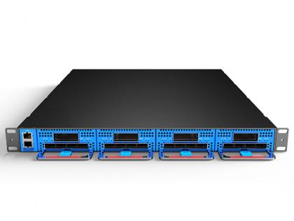 4x400G DCI BOX, 16*100G 1.6T transmission 1U Rack
 4x100G QSFP28 to 1x400G CFP2 DCO TMUX board FW841
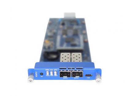 400G DCI Box Network management Control Board FW8N
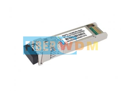 SFP+ 10G BIDI 80KM 1490/1550nm Optical Transceiver
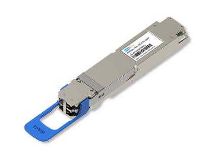 OSFP-800G-2LR4 PAM4 CWDM4 Dual CS 10km SMF Optical Transceiver Module
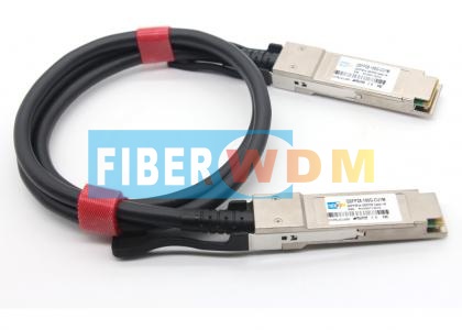 100G QSFP28 DAC Transceiver
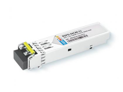 2.5G SFP CWDM 80km Optical Transceiver
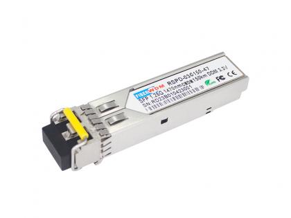 SFP 1.25G 1270-1610nm CWDM 150KM DDM Optical Transceiver

Address : Room 901, Building 6, JD Smart Industrial Park, No. 128, Juhua Stone Avenue, Huashan Town, Huadu District, Guangzhou City
Tel : +86 15989256178
Whatsapp : +86 15914235380
Email : sales@fiberwdm.com


