Fiberwdm's APD Avalanche Photodetector is fully domestically produced. Adopting an exclusive temperature compensation technical solution, it achieves high sensitivity. The detector maintains high stability, high gain, and low noise throughout the entire temperature range (-40°C to 80°C).
In addition to detectors with standard specifications, customized services are also provided. Various indicators of the detector (such as supply voltage, gain, bandwidth, etc.) can be adjusted according to customer needs to meet specific requirements.
Application Fields: Lidar, free-space optical communication, fiber optic sensing systems, optical detection systems, etc.
APD1008 Avalanche Photodetector
User Manual
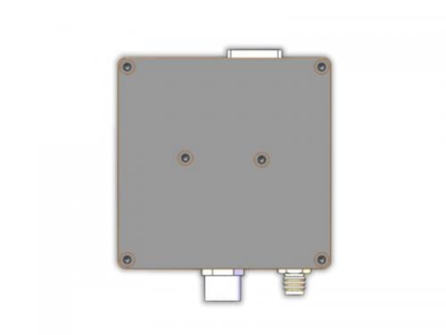
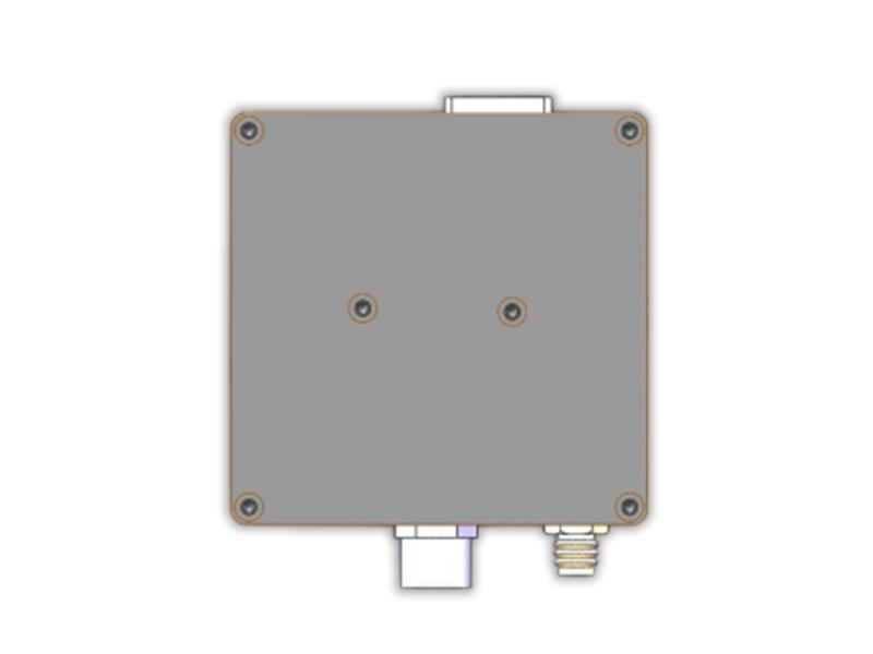
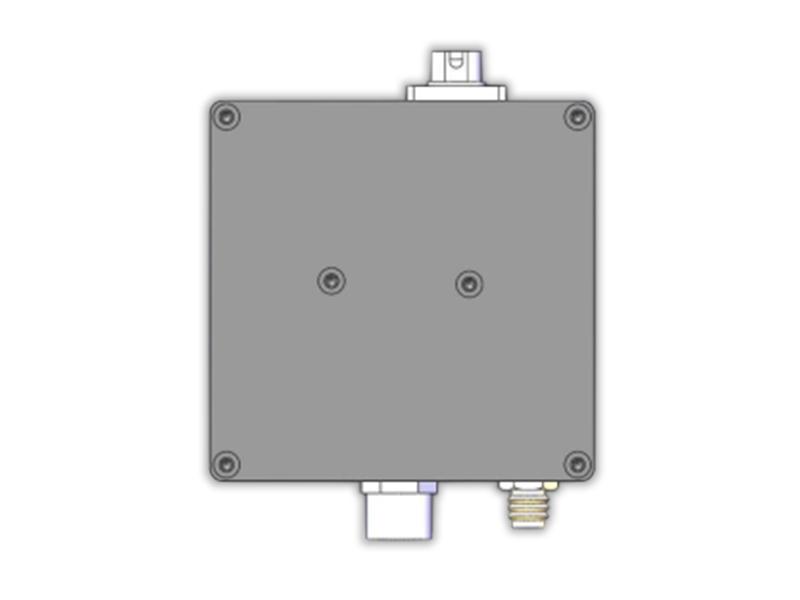
2.1 Appearance and Interface Description
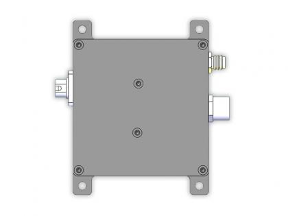
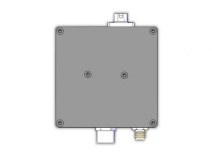
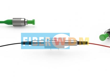
The appearance of the module is shown in the figure below:


Figure 2-1 Appearance Diagram of the Detector Module (Left: FC Connector, Right: Free Space)
The upper interface is the optical input interface (FC/Free Space), the lower right is the power input interface (M8/or lead wire output), and the lower right is the signal output interface (SMA).
The output of the version with temperature compensation is at the GH1.25 terminal, which is defined as follows:

Figure 2-2 Matching Power Cable
The interface definition is as follows:
|
Color |
Interface Definition |
|
Red |
+12V Input |
|
Black |
+12V_GND Input |
|
Green |
GND |
|
Blue |
Serial TTL_TX |
|
Yellow |
Serial TTL_RX |
Electrical Specifications
The APD module is a single power supply product: connect the red wire to 12V, the black wire to ground, with a current of 300mA. The current of the detector module during normal operation is less than 100mA.
1. Output Interface: SMA (Female);
2. Output Impedance: 50Ω;
3. Maximum Output Voltage:
Products below 500MHz: ±3.6V (@High Z), ±1.8V (@50Ω);
Products above 1GHz (inclusive): ±1V (@50Ω).
4. Spectral Response Range: 900nm - 1700nm;
5. Detector Responsivity: >0.95A/W @1550nm;
6. The optical input amplitude should not exceed the saturation power.
Performance Parameters
Performance Test Description:
1. Due to the different conditions of the FC connectors of the test light sources, the insertion loss of each detector varies, and the test results of the detector response will have slight differences;
2. The transimpedance gain of the detector is calculated under the condition that the output load is high impedance. If the output load is 50Ω, the gain is reduced to half of the nominal value;
3. The measurement results of detector noise and rise time are obtained under the following conditions:
a: Oscilloscope input impedance 50Ω;
b: Oscilloscope bandwidth is full bandwidth (≥1GHz);
c: Oscilloscope time division is set to 100ns/div (Note: Noise varies significantly with different time divisions);
4. Test ambient temperature: 23℃±5℃;
5. Test relative humidity: 35%±15%;
6. Test operating voltage: ±12V;
Typical Test Parameters of APD Detector (APD1008)
|
Model |
APD1008 |
|
Wavelength Range |
900-1700nm |
|
3-dB Bandwidth |
DC/AC-80MHz |
|
Conversion Gain |
600x103V/A |
|
Overall output voltage noise |
4mVRMS (typ) or 24mVpp |
|
Rise time |
1.9ns (typ) |
|
Saturation Power |
5uW(Maximum peak power) |
|
Typical Max. Responsivity |
9A/W @1550nm, M=10 |
|
Output Impedance |
50Ω |
|
Maxim Output |
1.5V@50Ω |
|
Incident Power (Max) |
100uW |
|
Detector Material/Type |
InGaAs/APD |
|
Detector Diameter |
50μm with ball lens |
|
Optical Input |
FC/PC or FC/APC or Free Space |
|
Electrical Output |
SMA |
|
Package Dimension |
58mm×58mm×25mm |
|
Power Supply Requirement |
12 V/200 mA |
Figure 3-1 Summary of Electrical Performance
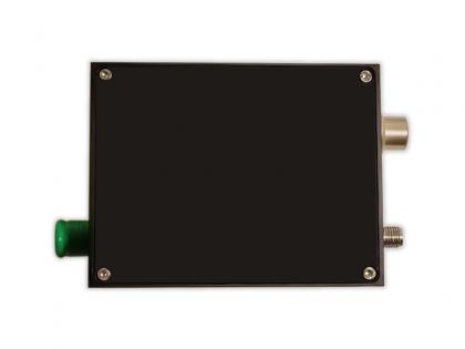
Mechanical Dimensions


Figure 4-1 Mechanical dimension diagram of APD detector module
Want to know about this product?
If you are interested in our products and want to know more details,please leave a message here,we will reply you as soon as we can.
 APD1050H Avalanche Detector
 APD2008 Avalanche Detector
 150GHz 8CH DWDM MUX DEMUX C38-H48(1556.555nm-1548.115nm) with Monitor Port,LC/UPC,LGX Box, and 4 Slots 1U Rack
 DAS Integrated Optical Module(Raman)
 M1x1 Magnet Fiber Optical Switch
 High-speed detector with amplification
APD2008 Avalanche Detector
High-speed detector with amplification
APD2008 Avalanche Detector
 1x2 PLC SC/UPC 2.0MM 1.0M Fiber DIN Mounting Box 120*110*20MM

Address : Room 901, Building 6, JD Smart Industrial Park, No. 128, Juhua Stone Avenue, Huashan Town, Huadu District, Guangzhou City
Tel : +86 15989256178
Whatsapp : +86 15914235380
Email : sales@fiberwdm.com


