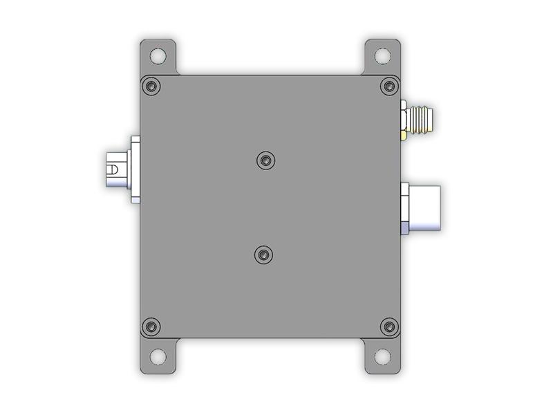
The APD Avalanche Photodiode Detector series has basically the same usage method as the avalanche detectors of Thorlabs and Newport, with completely identical power interfaces. It can be directly replaced when the Monitor output (available on some products of Thorlabs and Newport) is not required and the bandwidth is the same, and its performance in all aspects is not inferior to similar products of Thorlabs and Newport.
Fiberwdm's APD Avalanche Photodiode Detector is fully domestically produced. Adopting an exclusive temperature compensation technical scheme, it achieves a high-sensitivity detector with high stability, high gain, and low noise over the entire temperature range (-40°C ~ 80°C). In addition to detectors with conventional specifications, customized services are also provided. Various indicators of the detector (such as supply voltage, gain, bandwidth, etc.) can be adjusted according to customer needs to meet specific requirements.
Application Fields: Laser radar, free-space optical communication, optical fiber sensing systems, optical detection systems, etc.
Amplified Photoreceiver
APD1050H Avalanche Detector
Usage Instructions
Appearance and Interface Description
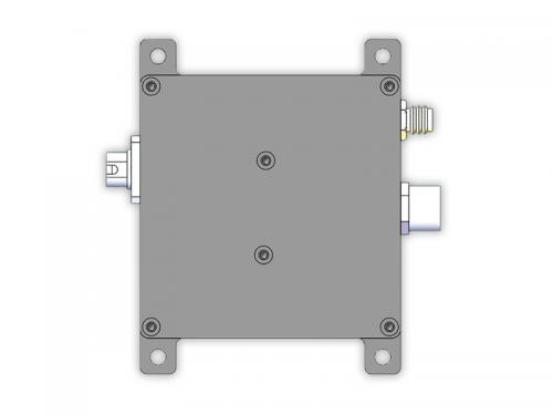
The appearance of the module is shown in the figure below:
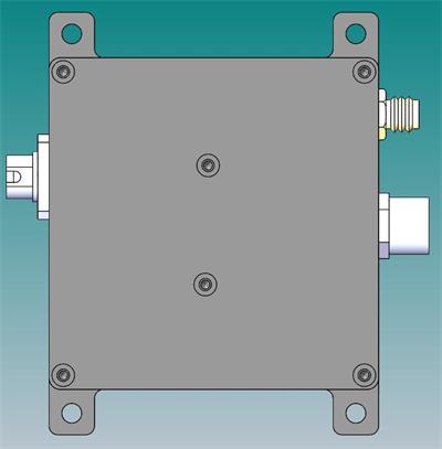
The left interface is the optical input interface (FC), the upper right is the power input interface (M8), and the lower right is the signal output interface (SMA).
The customized matched power cable is shown in the figure below:
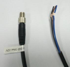
Figure 2-2 Matched Power Cable
The left end in the picture is the connection end to the detector module, with a label attached indicating the connection method of the 3 power cables on the right. The cable is made of PVC, with a maximum current of 3A and a wire gauge of 24AWG. Its pin definition is completely consistent with that of the power cables of Thorlabs and Newport's detector modules, and they can be used interchangeably.
Electrical Specifications
1. Dual-power supply products: ±12V (brown/red: +12V, black: GND, blue: -12V). For products with 300MHz and below, the minimum power supply voltage can be as low as ±8V, and the maximum should not exceed ±15V (if there is any inconsistency between the detector label and this manual, this manual shall prevail). For products above 1GHz, the supply voltage shall not exceed ±12V. In addition, the Honghai switching power supply module JMD10-D12 can be purchased as the test power supply module. This module can ensure the detector performance when used indoors; please evaluate it yourself when used outdoors. The current of the detector module during normal operation is less than 100mA.
Single-power supply products: 5V-12V (brown/red: +12V, black: GND, blue: floating). The current of the detector module during normal operation is less than 100mA.
2. Output interface: SMA (female);
3. Output impedance: 50Ω;
4. Maximum output voltage:
Products below 500MHz: ±3.6V (@High Z), ±1.8V (@50Ω);
Products with 1GHz (inclusive) and above: ±1V (@50Ω).
5. Spectral response range: 900nm-1700nm;
6. Detector responsivity: >0.95A/W @1550nm;
7. The optical input amplitude shall not exceed the Saturation Power.
Performance Parameters
Performance Test Instructions
1. Due to the different conditions of the FC connectors of the test light sources, the insertion loss of each detector is inconsistent, and the test results of the detector response will vary slightly;
2. The transimpedance gain of the detector is calculated when the output load is high impedance. If the output load is 50Ω, the gain will be reduced to half of the nominal value;
3. The measurement results of detector noise and rise time are obtained under the following conditions:
a: Oscilloscope input impedance 50Ω;
b: Oscilloscope bandwidth is full bandwidth (≥1GHz);
c: Oscilloscope time base is set to 100ns/div (Note: Noise will vary significantly with different time bases);
4. Test ambient temperature: 23℃±5℃;
5. Test relative humidity: 35%±15%;
6. Test operating voltage: ±12V;
Typical Test Parameters of Unit Detector (APD1050H)
| Model | APD1050H |
| Wavelength Range | 900-1700nm |
| 3-dB Bandwidth | DC-500MHz |
| Conversion Gain | 100x103V/A |
| Overall output voltage noise | 25mVpp(typ) |
| Saturation Power | 14uW |
| Typical Max. Responsivity | 1A/W @1550nm |
| Output Impedance | 50Ω |
| Maxim Output | 1.5V@50Ω |
| Incident Power (Max) | 0.5mW |
| Detector Material/Type | InGaAs/APD |
| Detector Diameter | 50μm with ball lens |
| Optical Input | FC/PC or FC/APC or Free Space |
| Electrical Output | SMA |
| Package Dimension | 58mm×58mm×25mm |
| Power Supply Requirement | 12 V/100 mA |
Figure 3-1 Summary of Electrical Performance
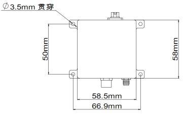
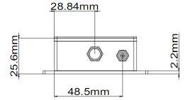
Mechanical Dimensions
Want to know about this product?
If you are interested in our products and want to know more details,please leave a message here,we will reply you as soon as we can.
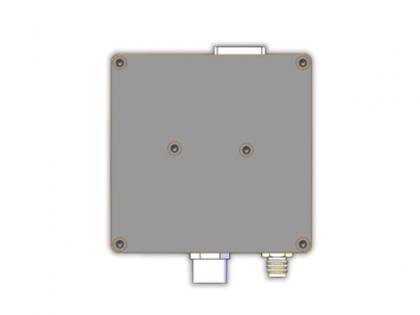 APD1008 Avalanche Photodetector
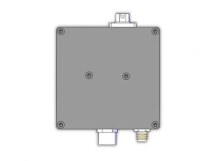 APD2008 Avalanche Detector
 Single Fiber 8CH (16Waves) O-BAND DWDM MUX DEMUX, LC/UPC, LGX Box, and 2 Slots 1U Rack
 XFP 10G DWDM 40km Transceiver
 10G Media Converter
 Dual Fiber 8CH C21-C28 DWDM MUX DEMUX
 8 OTAPs Passive Network Optical Taps Module
 10G ZR 80KM SFP+ Optical Transceiver

Address : Room 901, Building 6, JD Smart Industrial Park, No. 128, Juhua Stone Avenue, Huashan Town, Huadu District, Guangzhou City
Tel : +86 15989256178
Whatsapp : +86 15914235380
Email : sales@fiberwdm.com