
A monitoring network is installed every 2 kilometers at the national highway intersection, and the network is connected in a serial manner. However, if a fault or power outage is found at a node in the middle, it will cause all subsequent nodes to be interrupted and unable to communicate; When a traffic accident occurs on a later section of the road, relevant evidence cannot be retrieved, so the country has also proposed a requirement for the online monitoring rate of highway intersections/public security networks to reach over 98%. In response to the above issues, our company's FIBERWDM Ruidong Technology has developed and produced the FW-OLPB optical line protector, which can help improve the online monitoring rate of high-speed intersections/public security networks.
OLPB optical line protector is an automatic switching system applied in the field of fiber optic communication that can automatically bypass faulty network nodes. It can automatically identify the power supply status of network nodes, and switch the optical path instantaneously when the protected node loses power, thereby avoiding all obstacles to network nodes and maintaining normal system connectivity.
OLPB optical line protector can be applied to video monitoring scenarios on highways and tunnels, which can prevent a failure of one node in the middle from causing other nodes to be completely blocked, maintain normal communication and operation of other nodes, and thus provide the online rate of video monitoring equipment. The following application diagram:
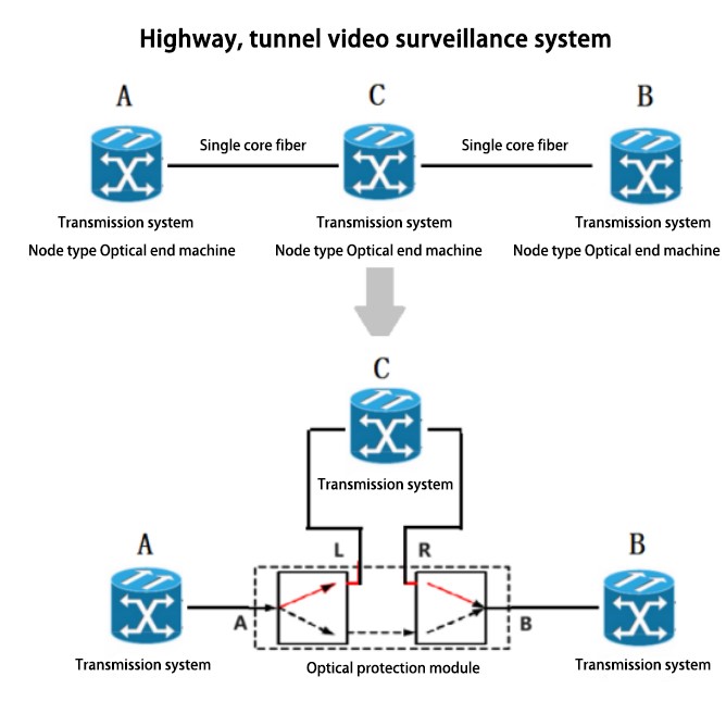
Adopting a single fiber chain network structure (as shown in Figure A-C-B), once a node in the middle fails (power failure), communication between all subsequent nodes will be interrupted;In order to increase the online rate of video surveillance on highways and tunnels Can be increase our company's production of light protectors OLPB to automatically bypass a faulty node (power failure) and ensure normal communication with other downstream nodes.
(1)Equipment A, C, and B are connected in a chain shape with a single fiberin the middle. If the equipment at point C loses power and fails, it will cause all communication services between equipment A and C to be interrupted.
(2) Add fiber protector OLPB:
Under normal circumstances:
A-end equipment - A interface (optical protection module) - L interface (C-point Equipment) - R (optical protection module) - B interface (optical protection module) - B-end Equipment
C-point Equipment power failure:
A-end equipment - A interface (optical protection module) - B interface (optical protection module) - B-end Equipment As shown in Figure (1):
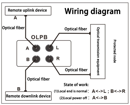
Figure (1)
When the C-point equipment loses power, the optical protection module automatically bypasses the node that experienced the power outage, ensuring normal communication between node A and node B. The bypass function is achieved through optical switching, which automatically switches the default path and transmits information flow in the event of power interruption. After the power supply at point C is restored, the system will automatically return to normal state (A-C-B).
|
index |
parameter |
|
Switching time(ms) |
< 15 |
|
Calibration wavelength (nm) |
1310&1550 |
|
Power range |
-50 ~ +23 dBm |
|
Accuracy |
± 5% |
|
Insertion loss (dB) |
<1.5 |
|
Crosstalk (dB) |
> 50 |
|
Return Loss(dB) |
> 45 |
|
Maximum passing optical power value (mW) |
300 |
|
Power consumption (W) |
< 5 |
|
Fiber |
Single mode |
|
Optical interface |
Four FC/PC |
|
Working temperature range (℃) |
-10 ~ 60 |
|
Storage temperature range (℃) |
-30 ~ 80 |
|
Working power supply |
DC: 5V~36V input (external power supply) |
|
Product type |
Independent modular or embedded in electrical cabinet box |
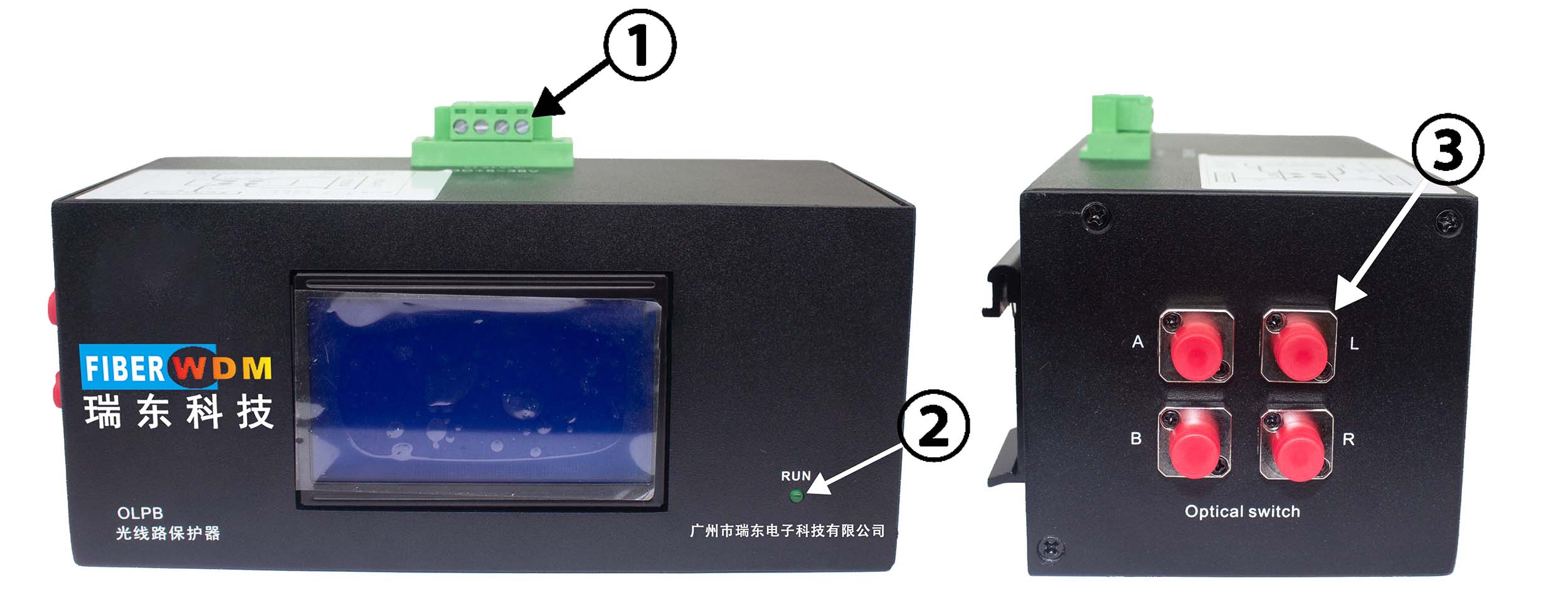
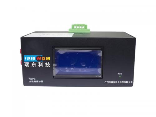
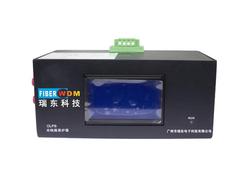
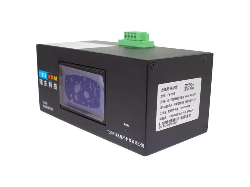
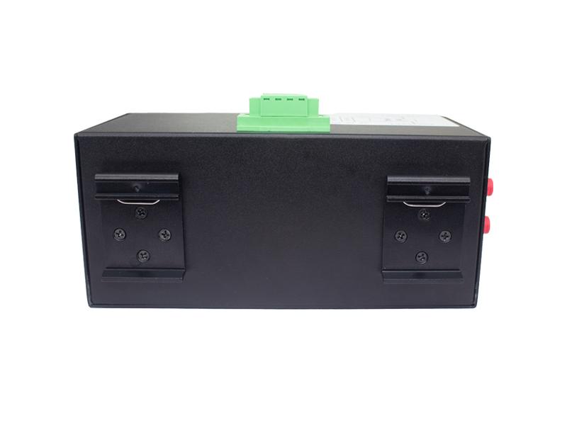
① POWER DC+5V-36V: Power input interface (external power adapter); Supports dual power supply access.
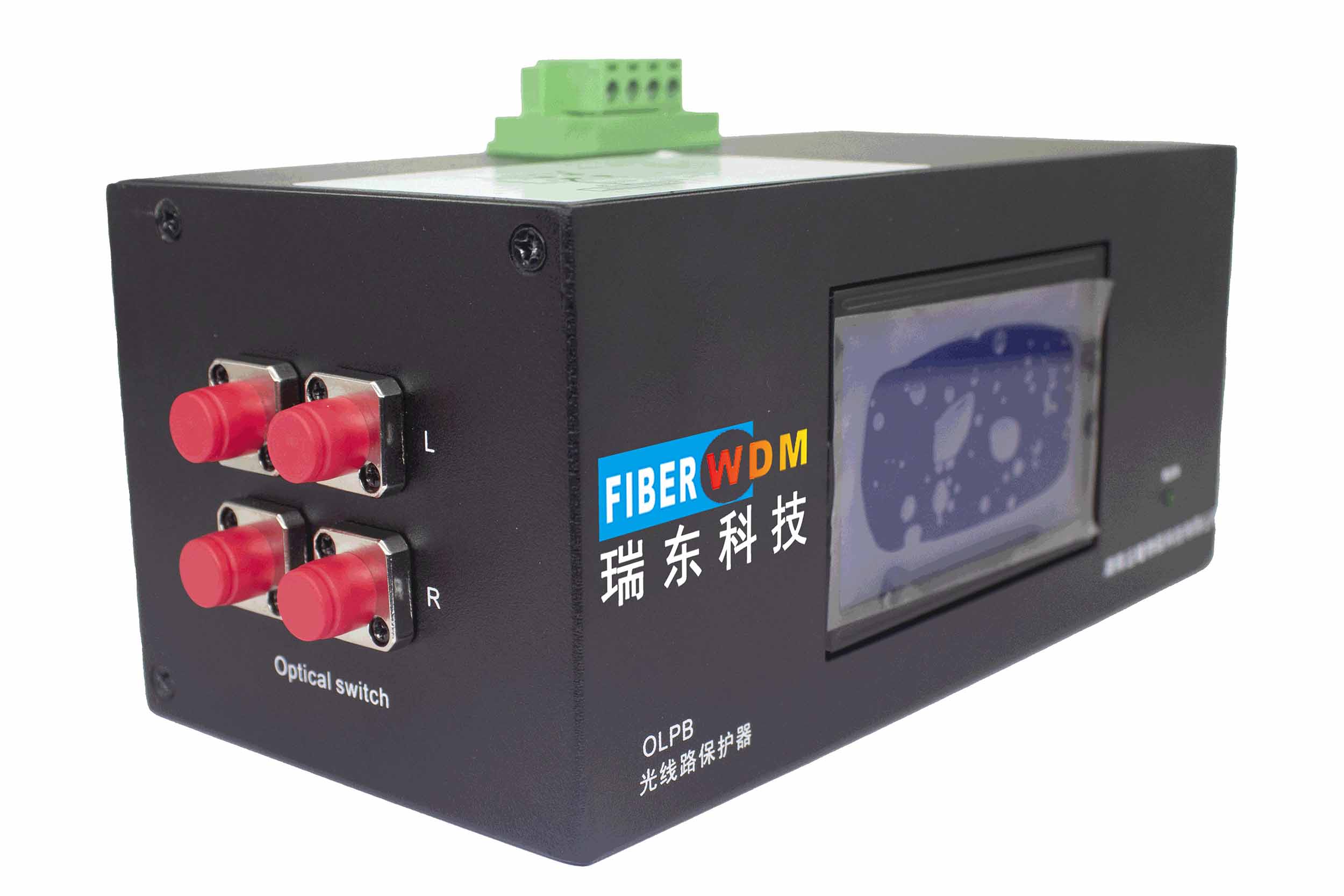
② ndicator light RUN: indicates the current working status, and when the light is on, it indicates that the equipment is normal and working on the main circuit; When the light is off, it indicates that the equipment is working in a bypass state.
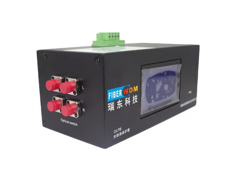
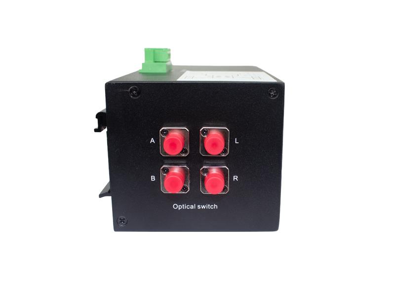
③ Optical Interface Description: There are four FC optical interfaces on the panel, namely A, B, L, and R. The specific connection method is as follows, please refer to the connection diagram (1).
Want to know about this product?
If you are interested in our products and want to know more details,please leave a message here,we will reply you as soon as we can.
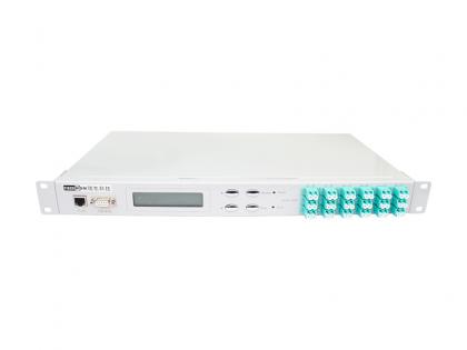 12 Channel 1×2 Optical Switch
 24 Channel 1×2 Optical Switch
 1 x N Multipath Channel Switch Device
 4 Channel 1×2 Optical Switch
 100Channel 1×2 Optical Switch
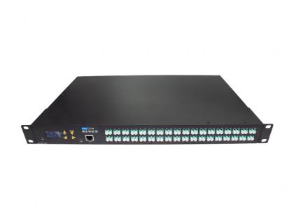
 32X32 Fiber Optical Switch 1270-1610nm SM LC/UPC 1U Rack
 Dual Fiber 8CH C29-C36 DWDM OADM, WEST TO EAST
 200G QSFP56 DAC Transceiver

Address : Room 901, Building 6, JD Smart Industrial Park, No. 128, Juhua Stone Avenue, Huashan Town, Huadu District, Guangzhou City
Tel : +86 15989256178
Whatsapp : +86 15914235380
Email : sales@fiberwdm.com


