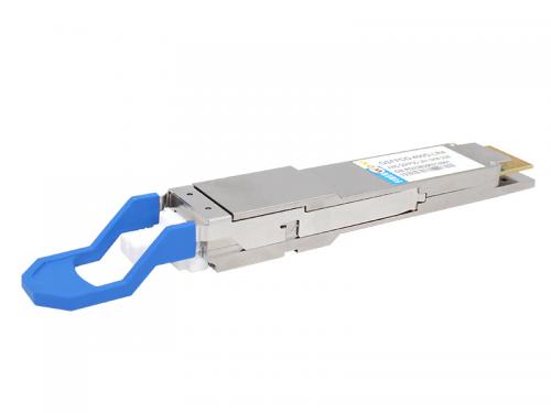

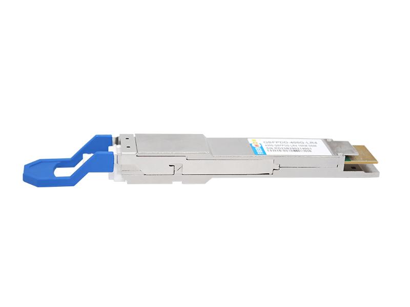
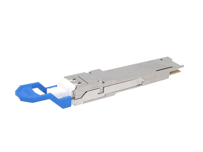
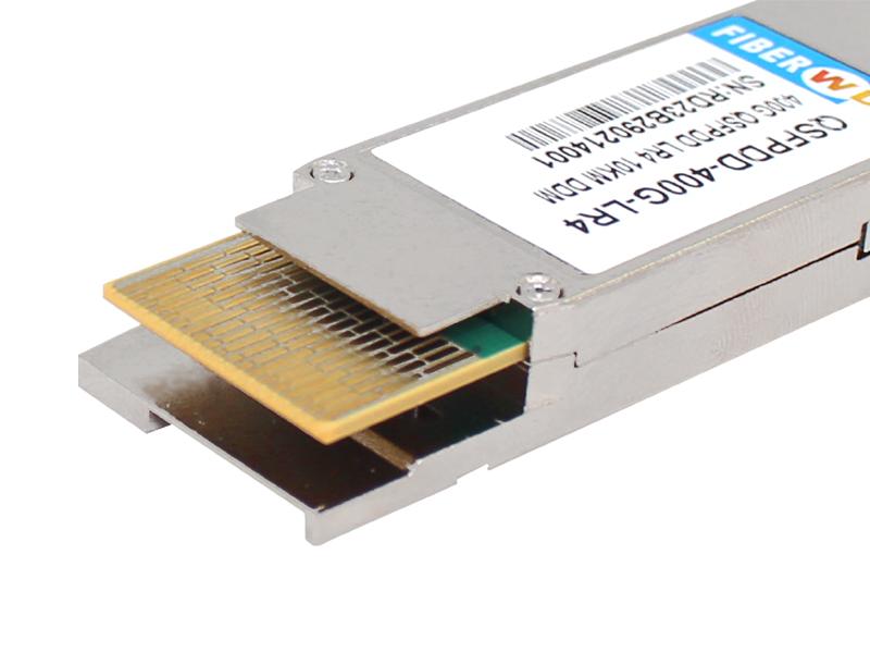
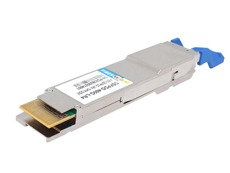
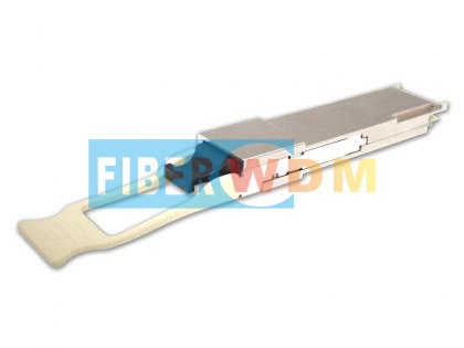
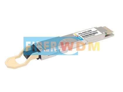
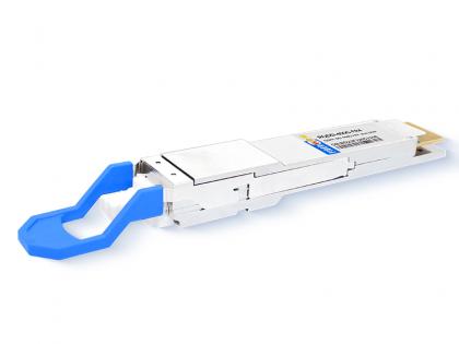
400G QSFP-DD LR4 optical transceiver module, support 400Gb/s and up to 10Km transmission on SM fiber, it works in high-speed IDC connection solutions.
Features
Applications
400G QSFP-DD LR4 CWDM4 10KMOptical Transceiver RQ-400G-LR4
FIBERWDM’s400Gb/s QSFP-DD optical module designed for 10km optical communication applications. The module converts 8 channels of 50Gb/s (PAM4) electrical input data to 4 channels of CWDM optical signals and multiplexes them into a single channel for 400Gb/s optical transmission.
On the receiver side, the module optically de-multiplexes a 400Gb/s optical input into 4 channels of CWDM optical signals and converts them to 8 channels of 50Gb/s (PAM4) electrical output data.
The central wavelengths of the 4 CWDM channels are 1271, 1291, 1311 and 1331 nm as members of the CWDM wavelength grid defined in ITU-T G.694.2.
Host FEC is required to support up to 10km fiber transmission.
1. Absolute Maximum Ratings
|
Parameter |
Symbol |
Min |
Max |
Unit |
|
Storage Temperature Range |
TSTG |
-40 |
+85 |
⁰C |
|
Supply Voltage |
VCC |
0 |
4 |
V |
|
Relative Humidity |
RH |
10% to 90% |
||
|
|
|
non-condensing |
||
2. Operating Conditions
|
Parameter |
Symbol |
Min |
Max |
Unit |
|
Case Temperature- Operating |
TCASE |
0 |
70 |
⁰C |
|
Supply Voltage |
Vcc |
3.14 |
3.46 |
V |
|
Power Consumption |
PDISS |
|
12 |
W |
|
Pre-FEC Bit Error Ratio |
|
|
2.4x10⁻⁴ |
|
|
Link Distance |
2 |
|
10,000 |
M |
3. Optical Characteristics
|
Transmitter Parameter |
Lane |
Min |
Typical |
Max |
Units |
|
Lane Wavelength Range |
Lane 0 |
1264.5 |
1271 |
1277.5 |
nm |
|
Lane 1 |
1284.5 |
1291 |
1297.5 |
nm |
|
|
Lane 2 |
1304.5 |
1311 |
1317.5 |
nm |
|
|
Lane 3 |
1324.5 |
1331 |
1337.5 |
nm |
|
|
Signal rate per lane |
|
|
53.125 |
|
GBd |
|
Average launch Power per lane |
|
-2.7 |
|
5.1 |
dBm |
|
Total Average launch power |
|
|
|
11.1 |
dBm |
|
Outer Optical Modulation Amplitude (OMAouter), each lane
for TDECQ<1.4 dB
for 1.4dB<=TDECQ<=3.9dB
|
|
0.3
-1.1+TDECQ
|
|
4.4 |
dBm |
|
Difference in launch power between any two lanes (OMAouter) |
|
|
|
4 |
dB |
|
Average Launch Power per Lane @ TX Off State |
|
|
|
-16 |
dBm |
|
Transmitter Eye Closure for PAM4(TECQ), each Lane |
|
|
|
3.9 |
dB |
|
Transmitter and dispersion Eye Closure for PAM4(TDECQ), each Lane |
|
|
|
3.9 |
dB |
|
|TDECQ – TECQ| |
|
|
|
2.5 |
dB |
|
Extinction Ratio |
|
3.5 |
|
|
dB |
|
Relative Intensity Noise (OMA) |
|
|
|
-136 |
dB/Hz |
|
Side-Mode Suppression Ration (SMSR) |
|
30 |
|
|
dB |
|
Optical Return Loss Tolerance |
|
|
|
15.6 |
dB |
|
Transmitter Reflectance |
|
|
|
-26 |
dB |
|
Transmitter over/under-shoot |
|
|
|
25 |
% |
|
Transmitter peak-to-peak power |
|
|
|
5.2 |
dBm |
|
Transmitter transition time |
|
|
|
17 |
ps |
|
Receiver Optical Specifications |
|
|
|
||
|
|
|
|
|
|
|
|
Receiver Parameter |
Lane |
Min |
Typical |
Max |
Units |
|
Lane Wavelength Range |
Lane 0 |
1264.5 |
1271 |
1277.5 |
nm |
|
Lane 1 |
1284.5 |
1291 |
1297.5 |
nm |
|
|
Lane 2 |
1304.5 |
1311 |
1317.5 |
nm |
|
|
Lane 3 |
1324.5 |
1331 |
1337.5 |
nm |
|
|
Signal rate per lane |
|
|
53.125 |
|
GBd |
|
Damage Threshold |
|
6.1 |
|
|
dBm |
|
Average Receive Power, each lane |
|
-9 |
|
5.1 |
dBm |
|
Receiver Power, each lane (OMA) |
|
|
|
4.4 |
dBm |
|
Receiver Reflectance |
|
|
|
-26 |
dB |
|
Difference in receive Power between any Two Lanes(OMAouter) |
|
|
|
4.3 |
dBm |
|
Receiver Sensitivity each lane (OMAouter)
for TECQ<1.4dB
for 1.4dB<=TECQ<=3.9dB
|
|
|
|
-6.8
-8.2+TECQ
|
dBm |
|
Stressed Receiver Sensitivity (OMAouter), each |
|
|
|
-4.3 |
dBm |
|
Stressed Conditions for Stress Receiver Sensitivity |
|||||
|
Stressed Eye Closure for PAM4 (SECQ),Lane under Test |
|
|
3.9 |
|
dB |
|
OMAouter of each Aggressor Lane |
|
|
-0.4 |
|
dBm |
4. Electrical Characteristics
|
Parameter |
Min |
Typical |
Max |
Unit |
Notes |
|
Receiver electrical output characteristics at TP4 |
|||||
|
Signaling rate per lane |
|
26.5625 |
|
GBd |
|
|
AC common-mode output voltage(RMS) |
|
- |
17.5 |
mV |
|
|
Differential peak-to-peak output voltage |
|
|
900 |
mV |
|
|
Near-end ESMW (Eye symmetry mask width) |
|
0.265 |
|
UI |
|
|
Near-end Eye height, differential |
70 |
|
|
mV |
|
|
Near-end vertical eye closure |
|
|
7.5 |
dB |
|
|
Far-end ESMW (Eye symmetry mask width) |
|
0.20 |
|
UI |
|
|
Far-end Eye height, differential |
30 |
|
|
mV |
|
|
Far-end vertical eye closure |
|
|
7.5 |
dB |
|
|
Far-end pre-cursor ISI ratio |
-4.5 |
|
2.5 |
% |
|
|
Common mode to differential conversion return loss |
802.3 Equation(83E-3) |
dB |
|
||
|
Differential output return loss |
802.3 Equation(83E-2) |
dB |
|
||
|
Differential termination mismatch |
|
|
10 |
% |
|
|
Transition time (min, 20% to 80%) |
|
9.5 |
|
ps |
|
|
DC common mode voltage |
-350 |
|
2850 |
mV |
|
|
Transmitter electrical input characteristics at TP1 |
|||||
|
Signaling rate, per lane |
|
26.5625 |
|
GBd |
|
|
Differential peak-to-peak input voltage tolerance |
900 |
|
|
mV |
|
|
Differential input return loss |
802.3 Equation(83E-5) |
|
|
||
|
Differential to common mode input return loss |
802.3 Equation(83E-6) |
mV |
|
||
|
AC common-mode output voltage(RMS) |
|
|
17.5 |
mV |
|
|
Single-ended voltage tolerance range |
-0.4 |
|
3.3 |
V |
|
|
Module stressed input |
802.3 120E.3.4.1 |
UI |
|
||
|
Differential termination mismatch |
|
|
10 |
% |
|
|
DC common mode voltage |
-350 |
mV |
|
||
5. Receiver Output Power Thresholds for Loss of Signal(LOS)
|
Parameter |
Min |
Typical |
Max |
Unit |
|
RX_LOS_Assert Min/Max |
-20.0 |
|
|
dBm |
|
RX_LOS_De-Assert Min/Max |
|
|
-12.2 |
dBm |
|
RX_LOS_Hysteresis |
0.5 |
|
|
dB |
6. Digital Diagnostic Monitoring Specifications
|
Temperature Monitor absolute error |
°C |
± 3 |
|
Supply Voltage Monitor absolute error |
% |
± 5 |
|
I_bias Monitor absolute error |
% |
± 10 |
|
Received Power (Rx) Monitor absolute error |
dB |
± 3.0 |
|
Transmit Power (Tx) Monitor absolute error |
dB |
± 3.0 |
7. Ordering information
|
Part Number |
Description |
|
RQ-400G-LR4 |
400G QSFP-DD LR4 CWDM4 10KM Optical Transceiver |
Want to know about this product?
If you are interested in our products and want to know more details,please leave a message here,we will reply you as soon as we can.
 400G QSFP-DD DR4 PAM4 1310nm 500M MPO Optical Transceiver
 400G QSFP-DD SR8 850nm MPO 100M Optical Transceiver
 400G CFP2 DCO Optical Transceiver Module
 QSFP112 400G BASE-SR4 850nm 100m Transceiver
 400G OSFP SR4 MM MPO12 Optical Transceiver IB
 400G OSFP DR4 SM MPO12 Optical Transceiver IB
 400G QSFP-DD FR4 2KM Optical Transceiver
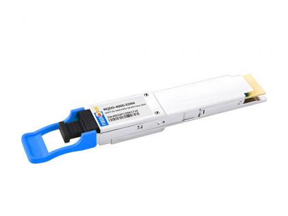 400G QSFP-DD EDR4 SM MPO12 2km Optical Transceiver

Address : Room 901, Building 6, JD Smart Industrial Park, No. 128, Juhua Stone Avenue, Huashan Town, Huadu District, Guangzhou City
Tel : +86 15989256178
Whatsapp : +86 15914235380
Email : sales@fiberwdm.com


