
Analog video signals and control signals can be converted into ultra-long-distance optical fiber signals, enabling long-range transmission with no latency and preventing wireless signals from being interfered with in specific ranges.
When used with a customized fiber optic spool, it can ensure that the drone flies 3/5/10/15/20/25/30 kilometers without interference.
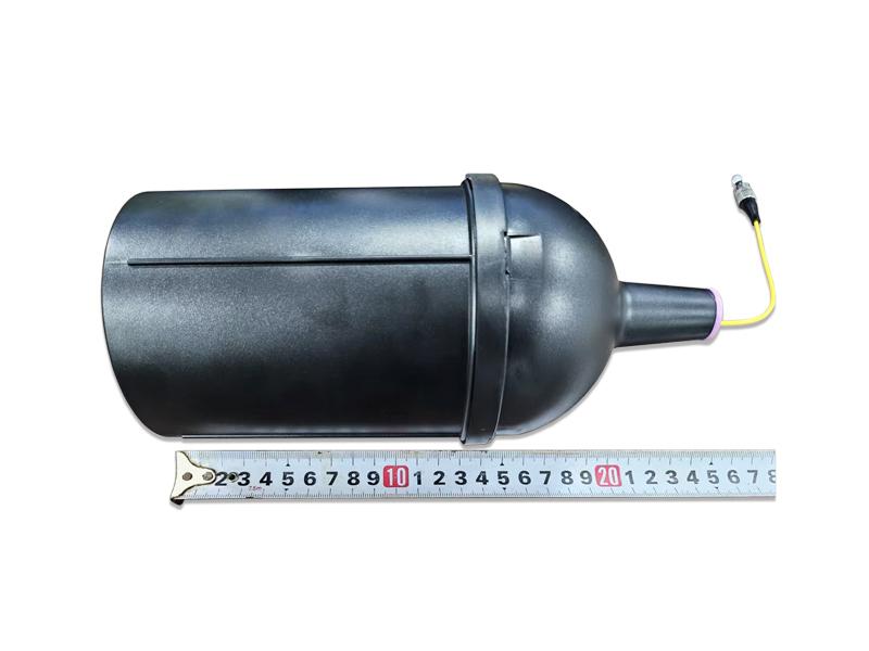
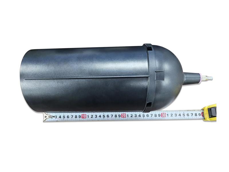
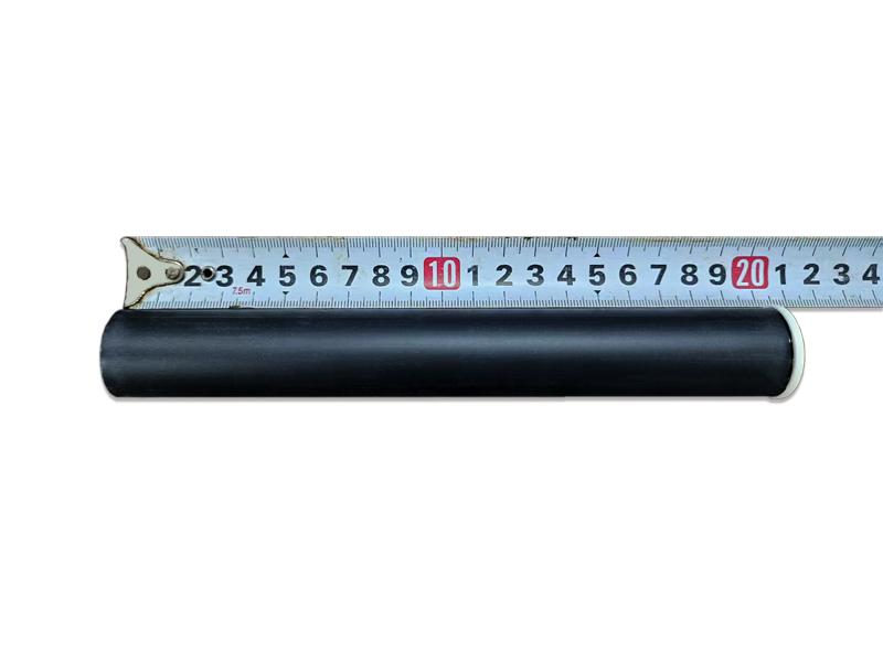
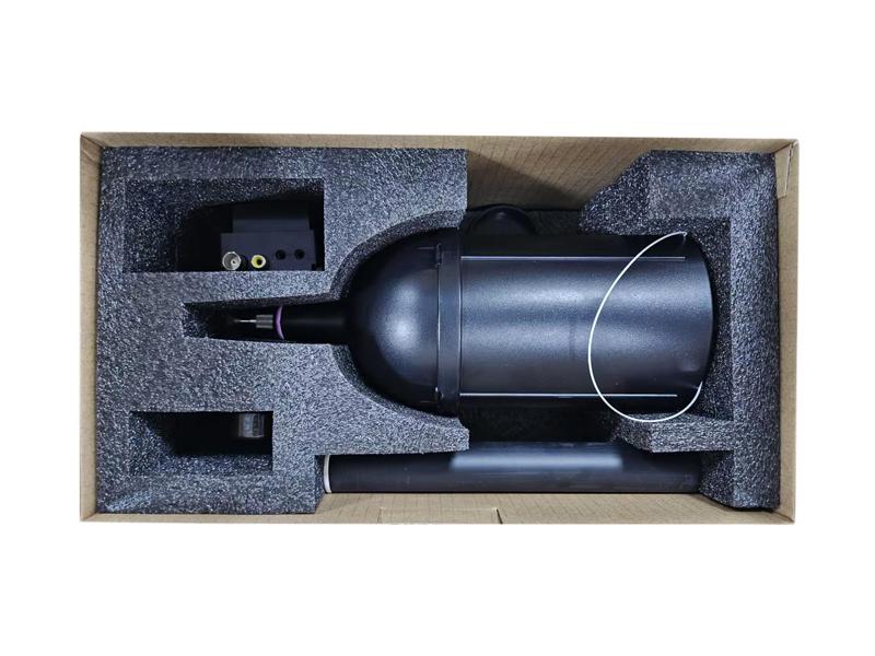
FPV Fiber Optic Spool
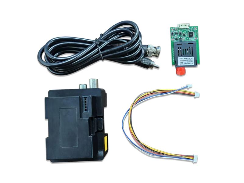
1. Sky and Ground Fiber Media Converter
1.1 Product Advantage
Fiber optic drones transmit data through physical cables, completely avoiding the threat of electromagnetic interference.
Optical fibers have extremely high data transmission bandwidth, enabling simultaneous transmission of multiple data streams. The light signals propagate at an extremely fast speed in optical fibers with extremely low latency, allowing real-time transmission of the drone's images.
Fiber optic drones do not radiate electromagnetic signals outward during flight. Their communication relies on light signal transmission inside the optical fiber, making them hardly detectable by the outside world and thus featuring outstanding concealment.
|
Sky Moudle |
Ground Moudle |
|
Fiber Optical Signal Transmitter |
Fiber Optical Signal Receiver |


2. FPV Drone Fiber Optic Spool

2.1 Specification Parameters
2.1.1 Optical Signal Transmitter (TX)
|
Parameter Category |
Details |
|
Input Power |
9-30V |
|
Interfaces |
UART and Video 1.0mm 6P |
|
Video Protocols |
PAL/NTSC |
|
Control Protocol |
S.BUS / CRSF |
|
Transmission Distance |
20/40/60KM |
|
Wavelength |
1310nm/1550nm |
|
Dimensions |
33mm×53mm×14mm |
|
Weight |
16g |
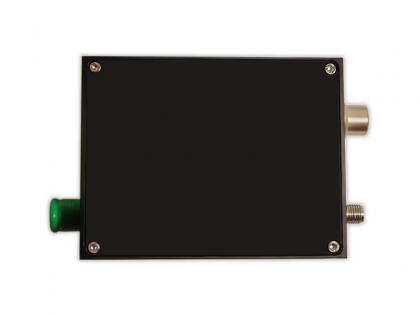
2.1.2 Optical Signal Receiver (RX)
|
Parameter Category |
Details |
|
Input Power |
9-30V |
|
Interfaces |
Video BNC RCA |
|
Video Protocols |
PAL/NTSC |
|
Control Protocol |
S.BUS / CRSF |
|
Transmission Distance |
20/40/60KM |
|
Wavelength |
1310nm/1550nm |
|
Dimensions |
57mm×92mm×48mm |
|
Weight |
70g |
3.Default Setup:
Diagram of Sky Module Connection
Fiber Optic Spool Flight Controller

4. Connection Instructions & Diagrams
Embedded sky module transmitter(TX) MX1.25MM 6P connects to the flight controler.
|
Sky Module Transmitter |
Flight Controller |
|
GND |
GND |
|
VCC |
5V-9V DC |
|
TX |
TX |
|
RX |
RX |
|
GND |
GND |
|
VIDEO |
VTX |
The ground station can be controlled via two methods: wireless CRSF and wired SBUS, with only one control method allowed per flight.

Note: The pictures are for reference only; the specific wiring method shall be subject to the flight controller board.
Speed setting serial number and RX port number
Which UART to use depends on the definition of the flight control board

Set the receiver protocol to UART and SBUS/CRSF

5.Ground Module
The ground station can be controlled via two methods: wireless CRSF and wired SBUS, with only one control method allowed per flight.
Note that the wireless mentioned here refers to the fact that the ground end and the remote controller use a wireless connection, while the sky and the ground end are still connected via wire.
Introduction and definition of the ground module interface
1.Analog signal interface
(1)TRRS interface
Due to the TRRS interface, there are two different interface definitions available on the market. The ground terminal is equipped with two TRRS interfaces. When connecting a display device using the TRRS interface, if the display device shows no image, please try the other TRRS interface.
(2)RCA interface
When the display device has an RCA interface, use the RCA interface on the ground terminal for connection.
(3)BNC interface
When the display device has a BNC interface, use the BNC interface on the ground terminal for connection.
2.Remote control (CRSF Receiver)
If using the CRSF protocol for communication control, this interface needs to have a CRSF receiver plugged in.
3.Video transmission interface
If wireless video transmission is required, this interface needs to have a wireless video transmission module plugged in.

6.Settings for connecting when using SBUS
Flight control setting
1.The flight control firmware needs to be burned as the SBUS version.
2.Flight control’s UART selection: In the port selection page, the UART needs to be selected as Serial Rx which UART to use depends on the UART currently used by the flight control board when connecting to the sky end.
Sky end connection
The FC port at the top of the sky is embedded in the optical fiber tube, while the other end has 6-pin 1.25mm pins. It needs to be connected to the corresponding position according to the UART interface of the flight control board.
Ground end connection
The ground end is directly embedded in the JR compartment of the TX12 remote control. The FC port of the ground end is connected to the optical fiber released from the optical fiber tube. The analog signal interface at the ground end is select based on the actual display device in use, providing a TRRS cable and an RCA-to-BNC adapter cable. The ground end does not require an external power supply. It can directly use power from the remote controller. If the power supply to the remote controller is used, it is necessary to ensure that power supply of the remote controller is sufficient.
TX12 Remote Control Setting
The Internal RF setting of the remote control is OFF, the External RF setting is SBUS, the Refresh setting is Not inverted, and the Trainer mode is set to Master/Jack.

Tips:
(1)During flight, check whether the fiber output is smooth the fiber cable outlet is away from the propellers.
(2)Avoid rapid deceleration and rapid descent. Avoid small angle turns when descending. Avoid rapid descent when turning. These operations may cause the fiber to be cut by propellers easily.
(3)Avoid winding at small bending angles when the fiber is output.
(4)Flight speed to be controlled within 120km/h.
(5)Before flying, please ensure that the strap and clips of fiber spool has been released.
(6)When taking off, accelerate slowly, avoid too fast accelerating and turning at small angles during the entire flight. Otherwise, fiber is easily entangled into propellers. (7)If the power supply to the remote controller is used, it is necessary to ensure that power supply of the remote controller is sufficient.
Want to know about this product?
If you are interested in our products and want to know more details,please leave a message here,we will reply you as soon as we can.
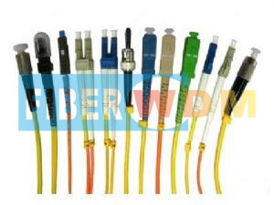
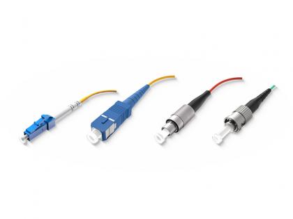 Optical Fiber Patch Cord
 Polarization Maintaining Fiber Patch Cord
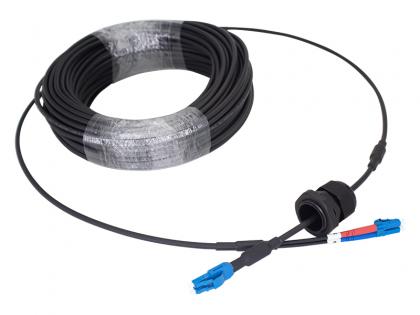 FTTA DLC-DLC-UPC SM 2C 5.0 ARMORED Cable
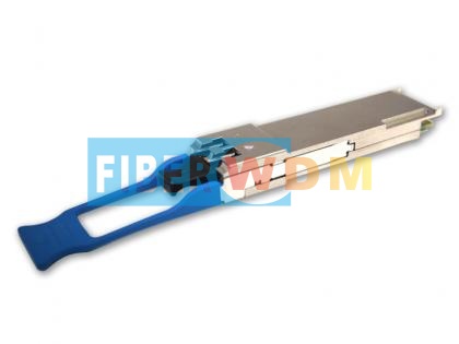 50G QSFP+ ER4 40Km 1310nm LC Optical Transceiver
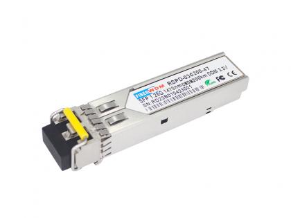 SFP 1.25G 1270-1610nm CWDM 200KM DDM Optical Transceiver
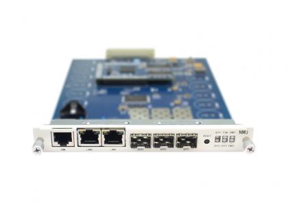 Network Management Unit (NMU)
 High-Speed Detectors HSPD4018 & HSPD4040
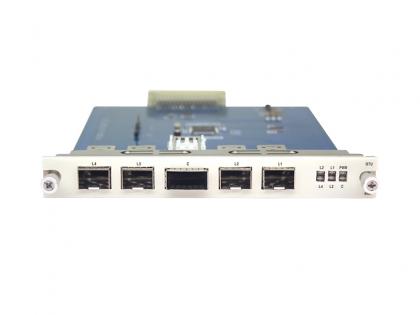 40G QSFP+ to 4x10G SFP+ Transponder Service Board

Address : Room 901, Building 6, JD Smart Industrial Park, No. 128, Juhua Stone Avenue, Huashan Town, Huadu District, Guangzhou City
Tel : +86 15989256178
Whatsapp : +86 15914235380
Email : sales@fiberwdm.com


