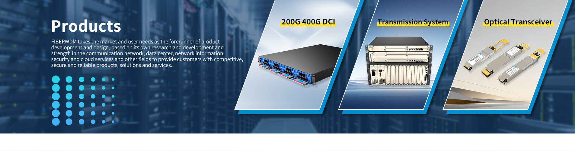
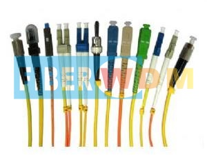

Polarization Maintaining (PM) Fiber Patch Cord
FIBERWDM’s Polarization Maintaining Fiber Patch Cord (PM Fiber Patch Cord) are available with FC, SC, LC connector options or as a pigtail assembly, center wavelength can be 780, 980, 1030, 1064,1310,1550nm and so on. PM Patch cords can be supplied in 250um bare fiber, 900um buffered fiber or 3mm cable. So the PM path cord are great use in Optical Fiber Amplifiers, Test Instrument, Fiber Sensor, Research, Fiber Laser.
Specifications
|
Parameter |
Unit |
Value |
||||||
|
Connector Type |
- |
FC, SC, LC |
||||||
|
Center Wavelength |
nm |
1550 |
1310 |
1060 |
980 |
850 |
780 |
|
|
Max. Insertion Loss |
nm |
0.3 |
0.3 |
0.5 |
0.5 |
0.8 |
0.8 |
|
|
Min. Extinction Ratio at 23℃ |
B |
23 |
23 |
23 |
23 |
22 |
22 |
|
|
Min. Return loss |
UPC Type |
B |
50 |
|||||
|
APC Type |
B |
60 |
||||||
|
Fiber Type |
- |
PM Panda fiber |
||||||
|
Key Orientation |
- |
Slow Axis |
||||||
|
Tolerance for Axis Alignment |
deg |
±3 |
||||||
|
Operating Temperature |
℃ |
-20~+70 |
||||||
|
Storage Temperature |
℃ |
-40~+85 |
||||||
The default connector key is aligned to slow axis.
Package Dimensions

Ordering Information
|
PMFP |
Axis Alignment |
Fiber Type |
Pigtail Type |
Fiber Length |
Connector for Input |
Connector for Output |
|
|
S:Slow axis |
01:PM1550 |
0:bare fiber |
05:0.5M |
LCU/A: LC/UPC or LC/APC |
LCU/A: LC/UPC or LC/APC |
|
|
F:Fast axis |
02:PM1310 |
1:900μm loose tube |
10:1M
|
SCU/A:SC/UPC or SC/APC |
SCU/A: SC/UPC or SC/APC |
|
|
|
03:PM980 |
2:2.0mm loose tube |
20:2M |
FCU/A: FC/UPC or FC/APC |
FCU/A: FC/UPC or FC/APC |
|
|
|
SS: Specify |
3:3.0mm loose tube |
30:3M |
N:None |
N:None |
|
|
|
|
|
200:20M |
S:Specify |
S:Specify |
|
|
|
|
|
S:Specify |
|
|
Want to know about this product?
If you are interested in our products and want to know more details,please leave a message here,we will reply you as soon as we can.
 Optical Fiber Patch Cord
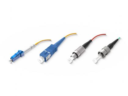
 FTTA DLC-DLC-UPC SM 2C 5.0 ARMORED Cable
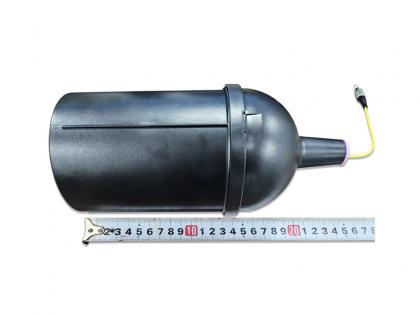 FPV Fiber Optic Spool
 APD2008 Avalanche Detector
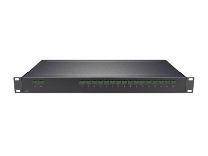
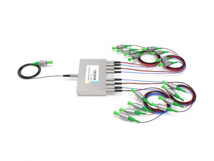 M1x16 Magnet Fiber Optical Switch
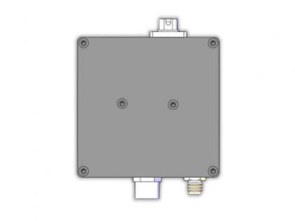
 4CH WDM GPON XGS-PON NG-PON2 And OTDR Plug-in LGX Box 215*150*20MM
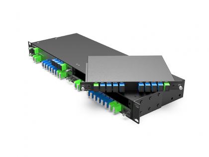
 Splitter PLC 2X16 SC/APC 1U Rack 440*200*44mm
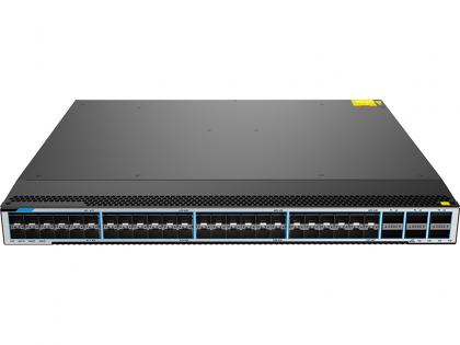 Data Center Switch 48x10Ge SFP+ ports and 6x40Ge QSFP+ uplink ports S6750-48X6QB-AC

Address : Room 901, Building 6, JD Smart Industrial Park, No. 128, Juhua Stone Avenue, Huashan Town, Huadu District, Guangzhou City
Tel : +86 15989256178
Whatsapp : +86 15914235380
Email : sales@fiberwdm.com


