Low Insertion Loss
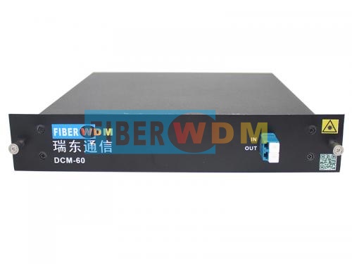
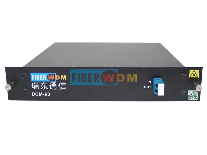
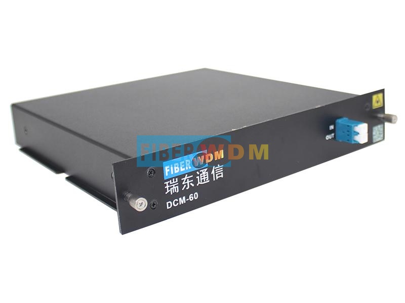
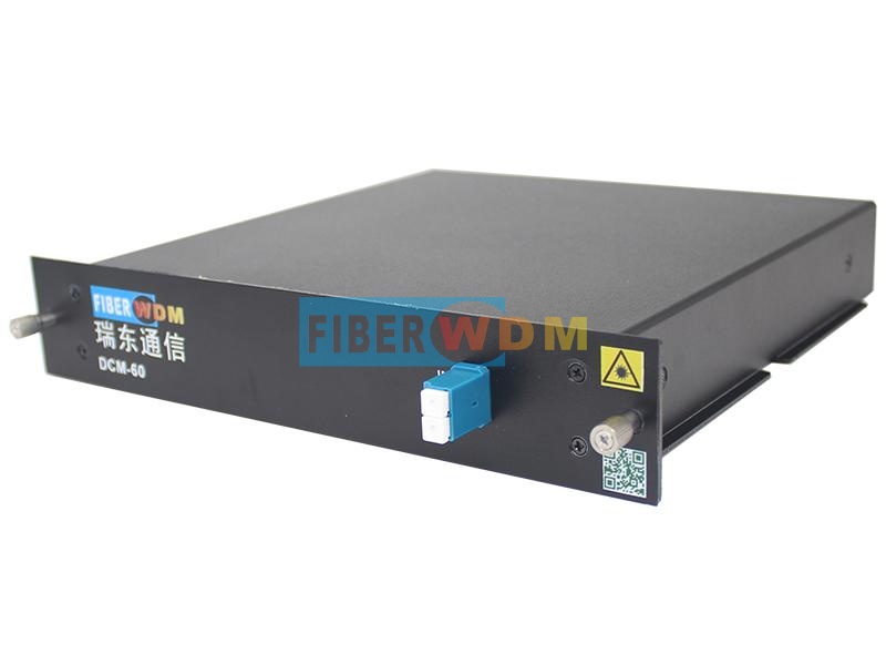
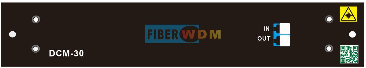
DCM- Dispersion Compensation Fiber Module
Dispersion Compensation Module (DCM) is designed to fix the form of optical signals that are deformed by chromatic dispersion. The main constituent of DCM is DCF (Dispersion Compensation Fiber) with a negative chromatic dispersion value within the wavelength range between 1525nm and 1565nm. The module offers a high level of compensation while maintaining a low flat insertion loss as well as a low latency. When combined with FIBERWDM's EDFA and OEO, DCM provides a simple, reliable, and cost-effective long-haul transport solution, making signals go further without regeneration.
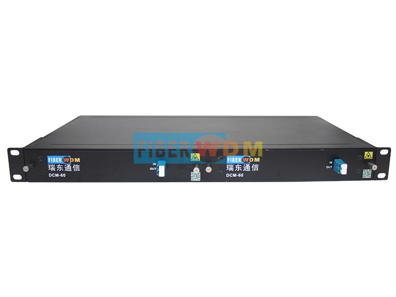
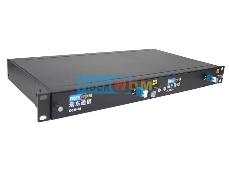
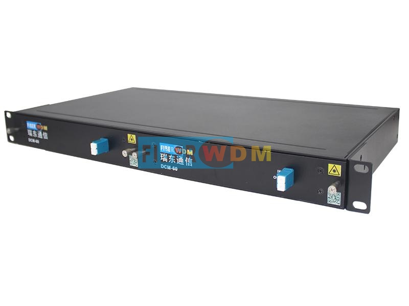
Product Penal
Applications
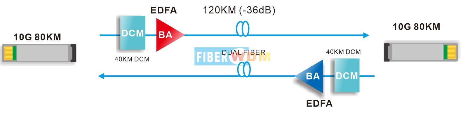
Application in Long-distance trunk network,or DWDM system
Specifications
|
Parametre |
Unit |
Value |
|||
|
mim |
typical |
max |
|||
|
Dispersion Value |
10KM |
ps/nm |
-320 |
-318 |
-340 |
|
20KM |
-336 |
-330 |
-346 |
||
|
40KM |
-650 |
-670 |
-690 |
||
|
60KM |
-970 |
-1000 |
-1030 |
||
|
80KM |
-1300 |
-1340 |
-1380 |
||
|
100KM |
-1630 |
-1680 |
-1730 |
||
|
120KM |
-1950 |
-2010 |
-2070 |
||
|
Center wavelength |
nm |
|
1550.12 |
|
|
|
Reflection Bandwidth(0.5dB) |
nm |
|
0.4 |
|
|
|
Insertion loss |
20KM |
dB |
|
|
3.5 |
|
40KM |
|
|
5.2 |
||
|
60KM |
|
|
6.8 |
||
|
80KM |
|
|
8.0 |
||
|
100KM |
|
|
9.5 |
||
|
120KM |
|
|
11.5 |
||
|
PMD |
ps |
|
|
1.0 |
|
|
PDL |
dB |
|
|
0.5 |
|
|
Wavelength Stability |
nm |
|
|
0.07 |
|
|
Package |
LGX Module |
||||
|
1U rack |
|||||
Package Information
|
DCM LGX boxModule |
2-slot 1U rack, support plug in 2 DCM module |
|
Product No. |
Product description |
|
DCM-10KM |
DCM 10KM LC/UPC Plug-in LGX Box |
|
DCM-20KM |
DCM 20KM LC/UPC Plug-in LGX Box |
|
DCM-30KM |
DCM 30KM LC/UPC Plug-in LGX Box |
|
DCM-40KM |
DCM 40KM LC/UPC Plug-in LGX Box |
|
DCM-60KM |
DCM 60KM LC/UPC Plug-in LGX Box |
|
DCM-80KM |
DCM 80KM LC/UPC Plug-in LGX Box |
|
DCM-100KM |
DCM 100KM LC/UPC Plug-in LGX Box |
|
DCM-120KM |
DCM 120KM LC/UPC Plug-in LGX Box |
|
1U02-2LGX |
19” inch 1U rack with 2 slot for Plug-in LGX box, 440*230*44mm |
Want to know about this product?
If you are interested in our products and want to know more details,please leave a message here,we will reply you as soon as we can.
 1550nm SOA Optical Pulse Modulation Module
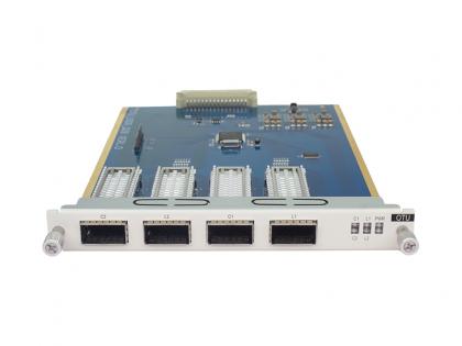 4X QSFP28 100G OTU/OEO Transponder Card
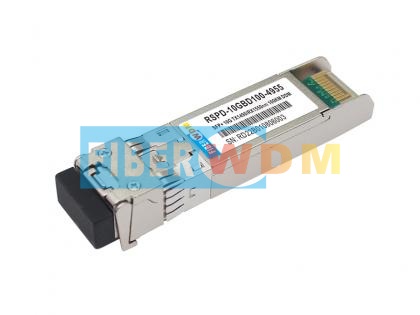 SFP+ 10G BIDI 100KM 1490/1550nm Optical Transceiver
 10 Gigabit Uplink Gigabit Managed POE Switch FW5700-48GP-4TF
 16Gbps FC DWDM SFP+ Transceiver, C-Band, EML, 40km Reach
 Splitter PLC 1X16 LC/APC Plug-in LGX Box 215*150*20MM
 800G QSFP-DD 2xLR4
 10/100/1000M External Media Converter 1*RJ45 and 1*SFP Port Switch

Address : Room 901, Building 6, JD Smart Industrial Park, No. 128, Juhua Stone Avenue, Huashan Town, Huadu District, Guangzhou City
Tel : +86 15989256178
Whatsapp : +86 15914235380
Email : sales@fiberwdm.com


