Features
Applications
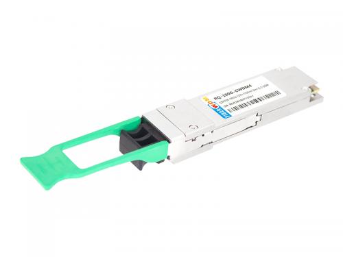
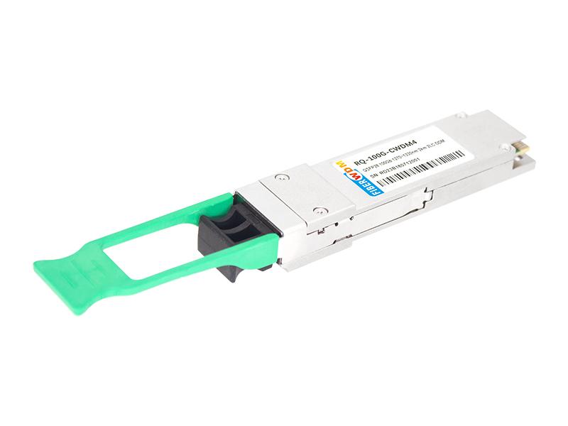
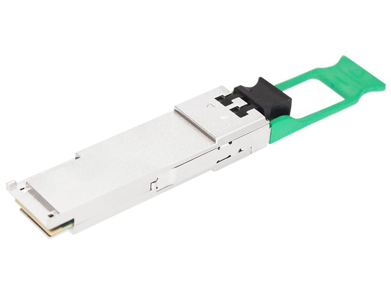
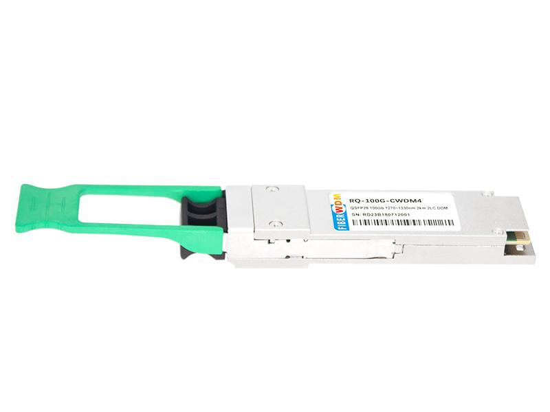
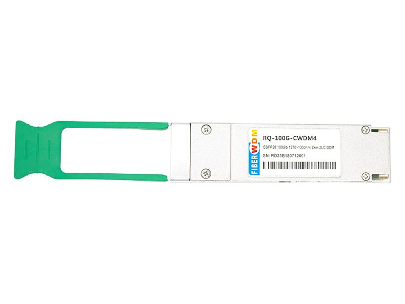
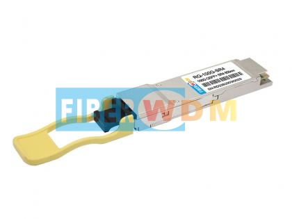
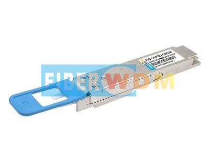
RQ-100G-CWDM4
100G QSFP28 CWDM4 2KM LC Optical Transceiver
FIBERWDM’s 100G QSFP28 CWDM4 is a 4x25G single-mode fiber, hot pluggable optical transceiver. FIBERWDM’s unique System On Glass TM (SOGTM) technology enables the integration of 4 transmitters, 4 receivers and an optical MUX/ DeMUX into a small form factor package that delivers a 100 Gbps data link in a compact QSFP28 footprint.
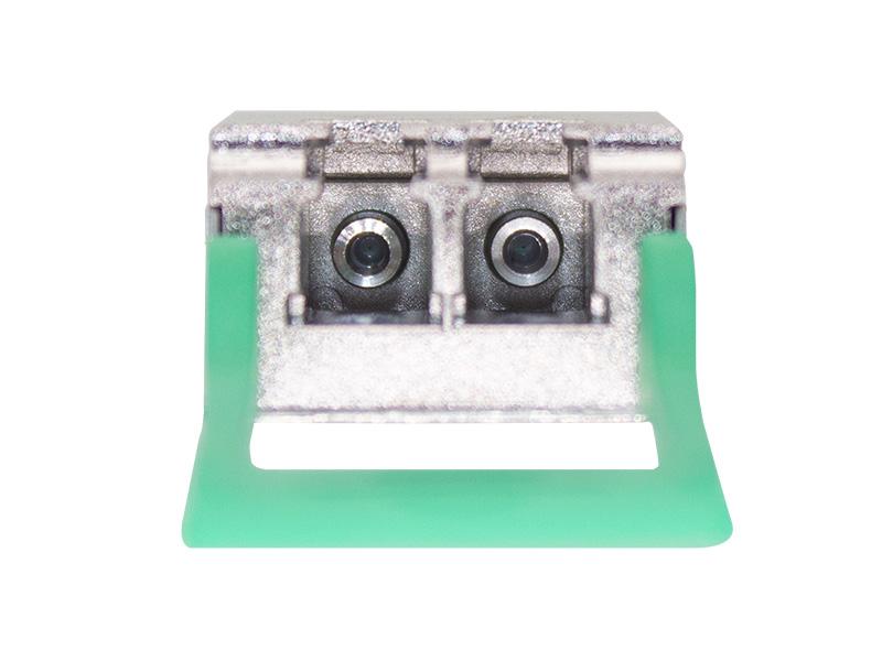
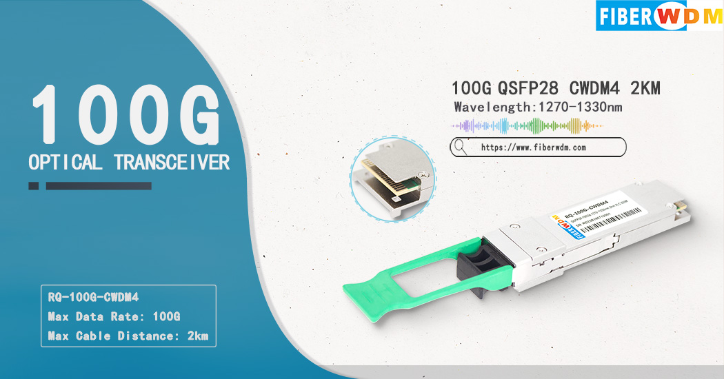
The optical connectivity is based on two Single mode Fiber (SMF) LC connectors, one for Tx and one for Rx. The Tx and Rx each consist of 4 25GB/s CWDM channels, whose wavelengths are in the 1300nm range. The QSFP28 CWDM4 transceiver is designed for applications with a reach up to 2000m and with the use of FEC.
This transceiver is based on proprietary FIBERWDM PLC technology, using surface mounted opto-electronic devices with no free space elements. The unique design of the optical engine facilitates unparalleled compactness while maintaining Telcordia robustness.
Revisions
|
Rev |
Date |
Description |
|
A |
Oct 27,2015 |
Initial Release |
|
B |
April 5, 2016 |
Updated mechanical design with modified pull tab |
|
C |
Sept 2, 2016 |
Modified mechanical design and Part Number |
|
D |
Dec.23th.2021 |
Update module pictures and drawing |
General Description
Compliant with the 100G CWDM4 MSA Technical Specification Rev 1.0
Supports 100 Gbps data rates links from 2m to 2km over a standard SMF
QSFP28 footprint (Quad Small Form-factor Pluggable) with 2 unidirectional LC SMF optical connector receptacles
Compliant to the SFF-8665 Pluggable Transceiver Solution (QSFP28) MSA
Electrical Interface based on CAUI-4 as defined by IEEE 802.3 CL83E
Compliant to the SFF-8636 Common Management Interface MSA
38 pin hot pluggable edge connector electrical interface
The transmitter consists of a retimed quad input, 4 un-cooled CWDM DFB lasers operating on the ITU G.694.2 wavelength grid at 1271, 1291, 1311 and 1331nm and multiplexed into a single SMF output
The receiver consists of a CWDM de-multiplexer, a quad photodiode receiver and a retimed electrical output
Provides Bias and Transmit Power Monitoring (TPM) for each of the 4 transmitter channels.
Provides RSSI Monitoring for each of the 4 receiver channels.
Provides monitoring of the voltage supplies and case temperature
Provides Module Present and Interrupt signals
Input control pins for Module Select, Module Reset and Low Power Modes
Supports operation for a case temperature of 0°C to +70°C
Includes customized coding option for module security implementation
Absolute Maximum Ratings
|
Parameter |
Symbol |
Min |
Max |
Units |
|
Storage Temperature Range |
TSTG |
-40 |
+85 |
℃ |
|
Supply Voltage |
Vcc |
O |
4 |
V |
|
Relative Humidity |
RH |
10% to 90% non-condensing |
||
Operating Conditions
|
Parameter |
Symbol |
Min |
Max |
Units |
|
Case Temperature- Operating |
TCASE |
3.14 |
70 |
℃ |
|
Supply Voltage |
Vcc |
|
3.46 |
V |
|
Power Consumption |
PDISS |
|
3.5 |
W |
|
Power Consumption- LP Mode |
PDISS-LP |
|
1.5 |
W |
Wavelength Lane Assignments
|
Transmitter Parameter |
Lane |
Min |
Typical |
Max |
Units |
|
Lane Wavelength Range |
Lane 0 |
1264.5 |
1271 |
1277.5 |
nm |
|
Lane 1 |
1284.5 |
1291 |
1297.5 |
nm |
|
|
Lane 2 |
1304.5 |
1311 |
1317.5 |
nm |
|
|
Lane 3 |
1324.5 |
1331 |
1337.5 |
nm |
Transmitter Optical Specifications
|
Transmitter Parameter |
Lane |
Min |
Typical |
Max |
Units |
|
Signaling rate, each lane |
|
25.78125±100ppm |
Gb/s |
||
|
Lane Wavelength Range |
Lane 0 |
1264.5 |
1271 |
1277.5 |
nm |
|
Lane 1 |
1284.5 |
1291 |
1297.5 |
nm |
|
|
Lane 2 |
1304.5 |
1311 |
1317.5 |
nm |
|
|
Lane 3 |
1324.5 |
1331 |
1337.5 |
nm |
|
|
Average Optical Power per lane |
|
-6.5 |
|
2.5 |
dBm |
|
Total Average Launch Power |
|
|
|
8.5 |
dBm |
|
Optical Modulation Amplitude (OMA), each lane |
|
-4 |
|
2.5 |
dBm |
|
Launch Power in OMA minus TDP, each lane |
|
-5 |
|
|
dBm |
|
Transmitter and Dispersion Penalty (TDP) each lane |
|
|
|
3 |
dB |
|
Average Launch Power per Lane @ TX Off State |
|
|
|
-30 |
dBm |
|
Extinction Ratio |
|
3.5 |
|
|
dB |
|
Relative Intensity Noise (OMA) |
|
|
|
-130 |
dB/Hz |
|
Side-Mode Suppression Ration (SMSR) |
|
30 |
|
|
dB |
|
Optical Return Loss Tolerance |
|
|
|
20 |
dB |
|
Transmitter Reflectance |
|
|
|
-12 |
dB |
|
Transmitter Output Power Monitoring Accuracy |
|
-3 |
|
3 |
dB |
|
Transmitter Eye Mask Definition X1, X2, X3, Y1, Y2, Y3) |
{0.31.0.4.0.45.0.34.0.38.0.4} |
|
|||
Receiver Optical Specifications
|
Receiver Parameter |
Lane |
Min |
Typical |
Max |
Units |
|
Signaling rate, each lane |
|
25.78125± 100ppm |
GB/S |
||
|
Lane Wavelength Range |
Lane 0 |
1264.5 |
1271 |
1277.5 |
nm |
|
Lane 1 |
1284.5 |
1291 |
1297.5 |
nm |
|
|
Lane 2 |
1304.5 |
1311 |
1317.5 |
nm |
|
|
Lane 3 |
1324.5 |
1331 |
1337.5 |
nm |
|
|
Damage Threshold |
|
3.5 |
|
|
dBm |
|
Average Receive Power, each lane |
|
-11.5 |
|
2.5 |
dBm |
|
Receiver Power, each lane (OMA) |
|
|
|
2.5 |
dBm |
|
Receiver Reflectance |
|
|
|
-26.0 |
dB |
|
Receiver Sensitivity (OMA) per lane at 5 x 10⁻⁵ BER |
|
|
|
-10.0 |
dBm |
|
RSSI Accuracy |
|
-3.0 |
|
3.0 |
dB |
Mechanical Drawings
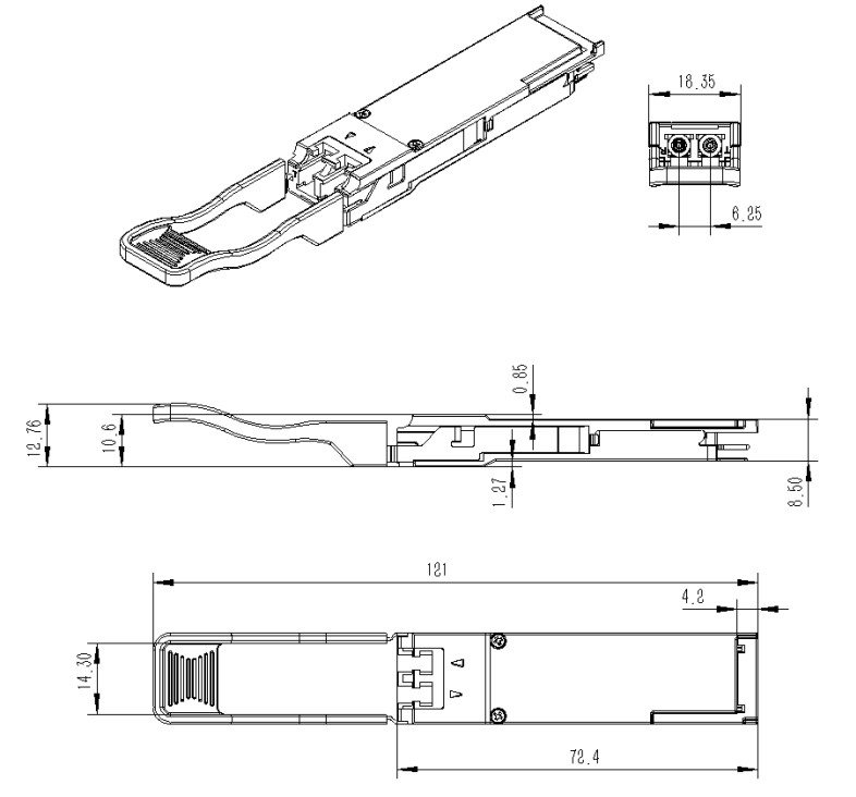
Figure 3. Mechanical Dimensions
Ordering information
|
Part Number |
Description |
|
RQ-100G-CWDM4 |
100G QSFP28 CWDM4 2KM LC Optical Transceiver |
Want to know about this product?
If you are interested in our products and want to know more details,please leave a message here,we will reply you as soon as we can.
 100G QSFP28 SR4 100m 850nm MPO Optical Transceiver
 100G QSFP28 CWDM4 10km LC Optical Transceiver
 100G QSFP28 LR4 1310nm 10km LC Optical Transceiver
 100G QSFP28 ER4 40Km 1310nm LC Optical Transceiver
 100Gb QSFP28 ZR4 80Km 1310nm LC Optical Transceiver
 100G LR1 10km SFP-DD Optical Transceiver
 100G DWDM QSFP28 Dual CS Connector PAM4 Transceiver
 100GBASE-SR Bi-Directional QSFP28 850/900nm 100m DOM LC MMF Optical Transceiver Module

Address : Room 901, Building 6, JD Smart Industrial Park, No. 128, Juhua Stone Avenue, Huashan Town, Huadu District, Guangzhou City
Tel : +86 15989256178
Whatsapp : +86 15914235380
Email : sales@fiberwdm.com


