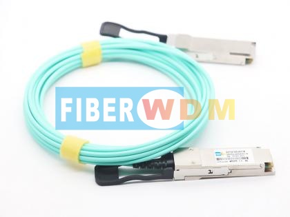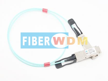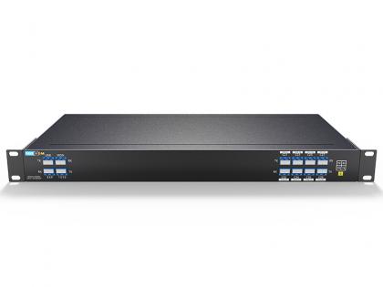
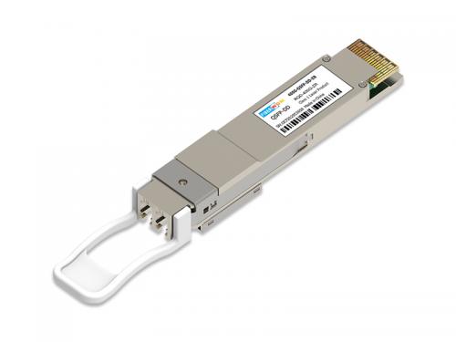
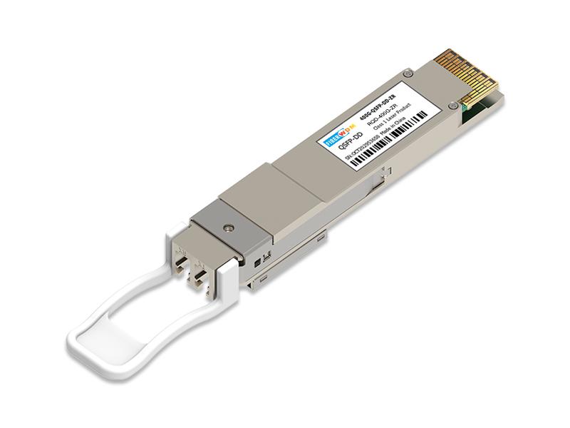
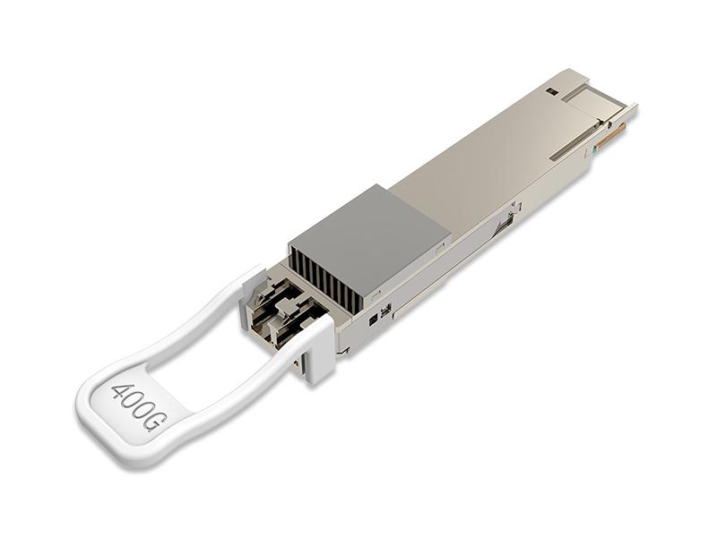
QSFP-DD transceiver modules are designed for N*400G DWDM transmission system. They are compliant with OpenZR+ standard and QSFP-DD MSA QSFP-DD Hardware Specification.
400G QSFP-DD ZR DCO RQD-400G-ZR
RQD-400G-ZR/ZR+ is QSFP-DD form factor single-carrier 100-400G coherent pluggable module, compliant tothe QSFP-DD MSA, QSFP-DD Hardware Specification, based on DP-16QAM modulation
, polarizationdiversity coherent Intradyne detection and advanced electronic link equalization.
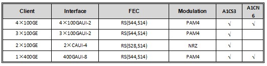
On the host side, the modulecan accommodate a variety of signal types including 4×100GE, 1× 200GE, and 1× 400GE modes. On the lineside,
the module supports 400G interfaces adapted with concatenated forward error correction (CFEC) codes and 100- 400G interfaces adapted with open forward error correction(OFEC).
400ZR+ QSFP-DD module is intended to be used in conjunction with a host platform to support DWDM transmission over optical links in DCI applications as illustrated in Figure 1. The module provides 400GE transport in industry standard small form factors,making this technology ideal for integration with high performance DCI fabric switches and routers.due to the integrated 100GE client multiplexing capabilities, it can be used as a highly integrated transponder for 4x100GE clients in data center interconnect applications.
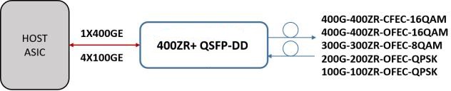
Figure 1 Module application diagram-400ZR+ Transceiver
The module is a complete implementation of a high performance coherent transceiver capable of operating in high performance telecom and datacenter.
The module operates as an Ethernet transceiver, supports 1×400GE and 4×100GE modesat the Host/ Client interface up to its configured line-side optical capacity.
Table 3 Line-side Mode
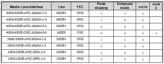
Table 4 Host-side Mode
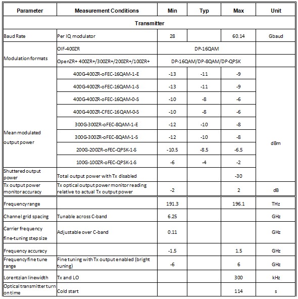
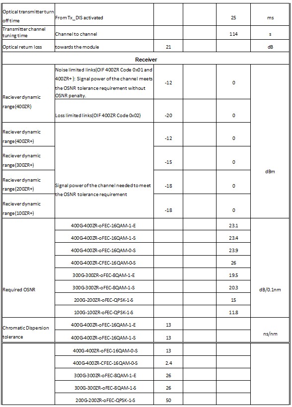
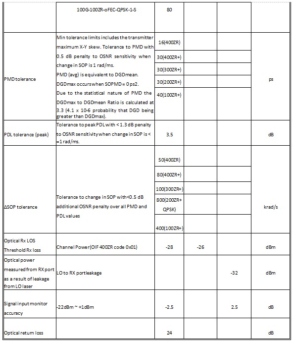
The module contains a PCB with connector consists of a single paddle card with 38 pads
on the top and 38 pads on the bottom of the paddle card for a total of 76 pads contact card-edge electrical interface to external Host/Client-side logic compliant to QSFP-DD Hardware Specification. The Network Lane Interface is a duplex LC connector coupled to an optical fiber carrying the DP-16QAM coherent signal in the C-band.
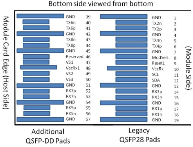
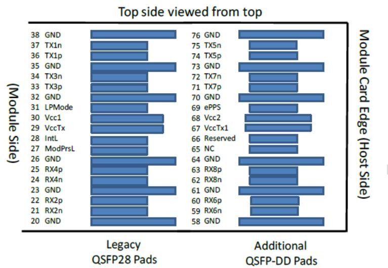
Figure 2 QSFP-DD module pinout
Table 6 Pin Descriptions
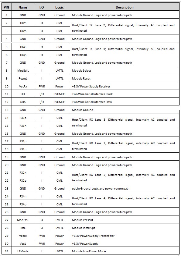
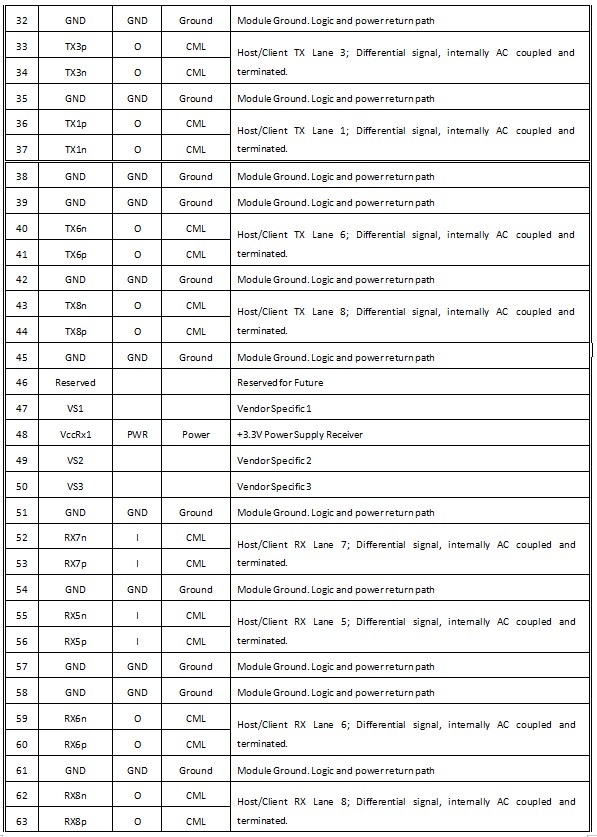
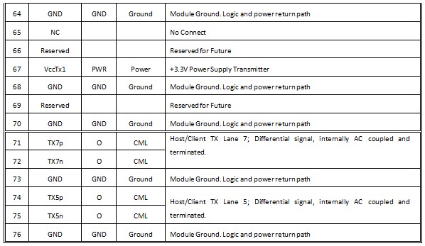
QSFP-DD uses common ground (GND)for all signals and supply (power). All are common within the QSFP-DD module and all module voltages arereferenced to this potential unless otherwise noted. Connect these directly
to the host board signal- common ground plane.
All Vendor Specific, Reserved, No Connect pins shall be left unconnected on the host.
Table 7 Low speed control and sense signals
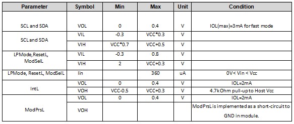
SCL and SDA
SCL and SDA are a 2-wire serial interface between the host and module using the I2C protocol. SCL is defined as the serial interface clock signal and SDA as the serial interface data signal. Both signals are open-drain, Low Voltage TTL (LVTTL) operating at Vcc, and require pull-up resistors to +3.3V on the host. The pull-up resistor value shall be 1k ohms to 4.7kohms depending on capacitive load.
ModSelL
The ModSelL is an input signal that is pulled to Vcc in the QSFP-DD module. When held low by the host, the module responds to 2-wire serial communication commands. When ModSelL is “High”, the module shall not respond to or acknowledge any 2-wire interface communication from the host.
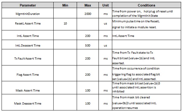
In order to avoid conflicts, the host system shall not attempt 2-wire interface communications within the ModSelL de-assert time after any QSFP-DD modules are deselected. Similarly, the host must wait at least for the period of the ModSelL assert time before communicating with the newly selected module. The assertion and de-asserting periods of different modules may overlap as long as the above timing requirements are met.
ResetL
The ResetL signal is pulled to Vcc in the module. A low level on the ResetL signal for longer than the minimum pulse length (t_Reset_init) initiates a complete module reset, returning all user module settings to their default state.
LPMode
LPMode is an input signal. The LPMode signal is pulled up to Vcc in the QSFP-DD module. LPMode is used in the control of the module power mode.
ModPrsL
ModPrsL is pulled up to Vcc Host on the host board and pulled low in the module. The ModPrsL is asserted “Low” when the module is inserted. The ModPrsL is de-asserted “High” when the module is physically absent from the host connector due to the pull-up resistor on the host board.
IntL
IntL is an output signal. The IntL signal is an open collector output and shall be pulled to Vcc Host on the host board. When the IntL signal is asserted Low it indicates a change in module state, a possible module operational fault or a status critical to the host system.
Table 8 Timing parameters for Host signals
Want to know about this product?
If you are interested in our products and want to know more details,please leave a message here,we will reply you as soon as we can.
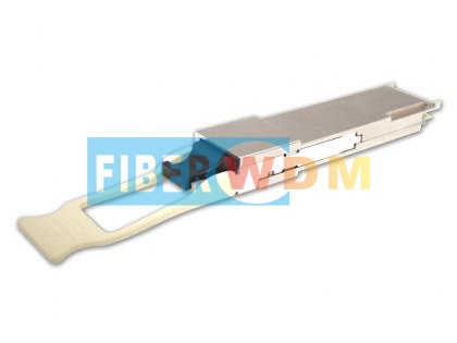 400G QSFP-DD DR4 PAM4 1310nm 500M MPO Optical Transceiver
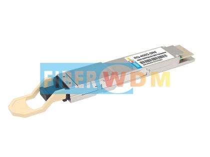 400G QSFP-DD SR8 850nm MPO 100M Optical Transceiver
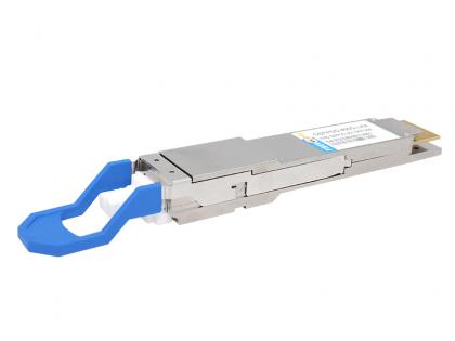 400G QSFP-DD LR4 10KM Optical Transceiver
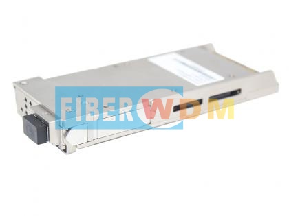 400G CFP2 DCO Optical Transceiver Module
 QSFP112 400G BASE-SR4 850nm 100m Transceiver
 400G OSFP SR4 MM MPO12 Optical Transceiver IB
 400G OSFP DR4 SM MPO12 Optical Transceiver IB
 400G QSFP-DD FR4 2KM Optical Transceiver

Address : Room 901, Building 6, JD Smart Industrial Park, No. 128, Juhua Stone Avenue, Huashan Town, Huadu District, Guangzhou City
Tel : +86 15989256178
Whatsapp : +86 15914235380
Email : sales@fiberwdm.com