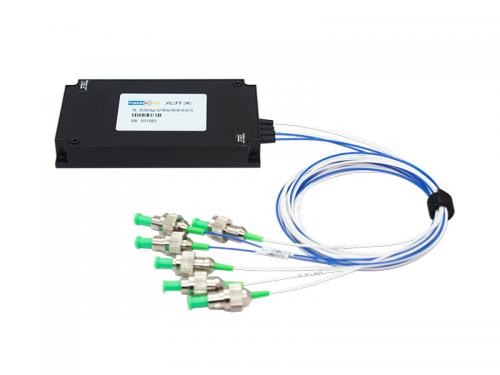
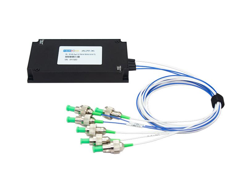
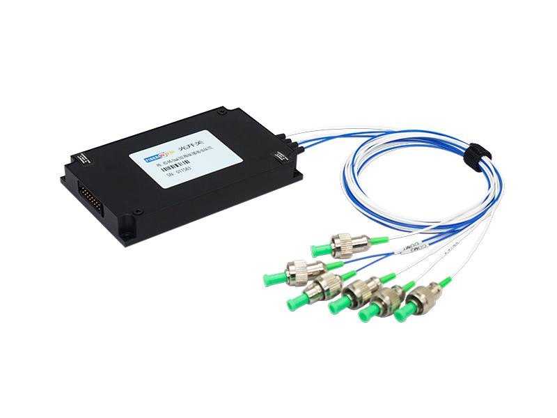
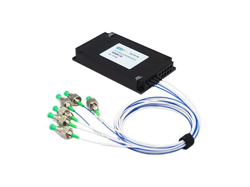
RD-MS-Dual-1×2-PM-M-780-90-10-FA-TTL PM Dual 1×2 MEMS Optical Switch is a high-performance polarization-maintaining fiber optical switch based on Micro-Electro-Mechanical Systems (MEMS) technology. It is specifically designed for fiber optic communication and sensing applications requiring strict polarization state maintenance. Featuring an advanced micro-mirror drive architecture, it offers ultra-low insertion loss, high extinction ratio, fast switching speed, and exceptional reliability. It is widely used in fiber optic sensing systems, precision optical measurement, laser scanning microscopy, Fiber Bragg Grating (FBG) monitoring, polarization-sensitive optical path switching, and other demanding applications.
Dual 1x2MEMS Switch(Module)
RD-MS-Dual-1×2-PM-M-780-90-10-FA-TTL
PM(Polarization-maintaining) Dual 1X2 MEMS Optical Swith,PM PM780,0.9mm loose
tube Fiber, FC/APC,TTL Control connection, 90x55x12mm
Applications
Environmental Conditions
| Parameters | Unit | Min | Max |
| Storage Temperature | ℃ | -40 | 85 |
| Operating Relative Humidity | %RH | 5 | 95 |
| Operating Temperature | ℃ | -5 | 70 |
| ESD Level (HBM) | V | 500 | |
| Max Power Handling | mw | 500 |
| Parameters | Unit | Specification |
| Channels | CH | Dual 1x2 |
| Testing Wavelength | nm | 780 |
| Insertion Loss | dB | ≤2.0(with connector) |
| Return Loss | dB | ≥50 |
| extinction ratio | dB | ≥16dB |
| Repeatability | dB | 0.03dB Max |
| Crosstalk | dB | ≥50 |
| PDL | dB | ≤0.15 |
| TDL | dB | ≤0.3 |
| Response Time | ms | ≤20 |
| Durability | Cycle | ≥1×10⁹ |
| Drive Voltage(Max) | V | 5~12 |
| Control Type |
TTL(Parallel /Serial Port Compatibility) The two switches are controlled on the same channel |
|
Notes:
1. The loss is based on the test results at 23℃.
2. Repeatability is defined after 100 cycles.
Pin Definition:
| Pin number |
Pin Assignment |
Signal Type | Description |
| 1 | D0 | Input | Data bit (D0) (low-order) |
| 2 | D5 | Input | Data bit (D5) |
| 3 | VCC | Power | Power Supply (DC 5V,1.0A) |
| 4 | D7 | Input | Data bit (D7) (high-order) |
| 5 | D6 | Input | Data bit (D6) |
| 6 | GND | Power | GND |
| 7 | D4 | Input | Data bit (D4) |
| 8 | D1 | Input | Data bit (D1) |
| 9 | TXD | Output | Data Transmit (TTL Level) |
| 10 | RXD | Input | Data Receive (TTL Level) |
| 11 | D2 | Input | Data bit (D2) |
| 12 | D3 | Input | Data bit (D3) |
| 13 | /BUSY | Output |
Low level means ready to reset or receiving data |
| 14 | /ALARM | Output | High level means running error |
| 15 | /STROBE | Input | Falling edge execution data bit |
| 16 | /RESET | Input | Low level reset to channel 0 |
Note: Molex 87833-1620 is used for the electrical interfaces of this modules and it is recommended to use Molex 87568-1694 for customer connectors.
This module can receive control signals through the UART interface to enable automated measurements or real-time monitoring.
(1). This module can only execute one instruction at a time. Typically, the next instruction can be entered only after the program returns the corresponding value.
(2) Please use capital letters.
(3) In practical operation, the angle brackets "<" and ">" are used as the start and end delimiters respectively.
(4). Instruction error returns <ER>.
Program Control Instruction Set
| Order | Describe | Example |
| <RESET> | Restart module | Successful return: <RESET_OK> |
| <RESTORE> | Reset | Successful return: <RESET_OK> |
| <INFO_?> | Query module information |
Return successfully: <MEMS-Dual-1X8_VER1.00_ SN01234567890_08.04.00051> Indicates MEMS-Dual-1X18 module, version 1.00, SN number 01234567890, product number 08.04.00051; |
| <BAUD_x> |
Set or query the serial port baud rate 1.x is 1~9, indicating baud rate 2400, 4800, 9600, 14400, 19200, 38400, 56000, 57600, 115200 respectively Successful return: <BAUD_x_OK> 2. Send <BAUD_?> to query the baud rate |
Send: <BAUD_5> Successful return: <BAUD_5_OK> Set the device serial port baud rate to 19200 The configuration will take effect after saving and rebooting! |
| <OSW_M_x> |
Working mode selection x: Values 0, 1, ?, 0 indicates data bit control switching, 1 indicates UART control switching, ? indicates query working mode; Successful return: <OSW_M_x_OK> |
Send: <OSW_M_1> Successful return: <OSW_M_1_OK> Indicates that the module is set to UART control switching;
Send: <OSW_M_?> Successful return: <OSW_M_1> Indicates that the module is UART controlled switching; |
| <OSW_01_SW_xxx> |
Set current channel xxx: The value is 000~256, 000 means 0 channel, 256 means 256 channel; Successful return: <OSW_01_SW_xxx_OK>
Note: In data bit control switching mode, Send: <OSW_01_SW_xxx> Return: <OSW_M_ER> |
Send: <OSW_01_SW_002> Successful return: <OSW_01_SW_002_OK> Indicates switching to channel 2; |
| <OSW_A_?> |
Query channel status Successful return: <OSW_A_Optical switch channel> |
Return: <OSW_A_001> Indicates that the optical switch is 1 channel; |
| <SAVE_ALL> |
Save configuration Successful return: <SAVE_ALL_OK> |
Save the configuration, such as saving the channel status. |
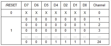
Data bit switching logic table
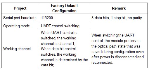
Factory default configuration
PCBA: D3-1 V56
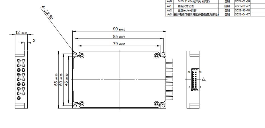
Mechanical Requirement (Units: mm)
| Parameters | Specification |
| Fiber Type | PM780,0.9mm loose tube |
| Fiber Length/Tolerance | 1+/-0.05m(without connector) |
| Connector | FC/APC |
| Channel markPM780,0.9mm loose tube |
White number tube with black font, Input--COM1,COM2 Output-- OUT1-1,OUT1-2,OUT2-1,OUT2-2 |
Want to know about this product?
If you are interested in our products and want to know more details,please leave a message here,we will reply you as soon as we can.
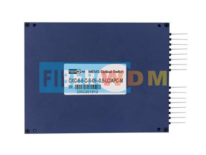 MXN MEMS Optical Switch
 MEMS Variable Optical Attenuator VOA
 1XN MEMS Optical Switch
 PM (Polarization-maintaining) 1X12 MEMS Fiber Optical Switch 1550nm 0.9MM 0.5M PM Fiber FC/APC 158x150x29nm Module
 1X10 PM MEMS optical switch
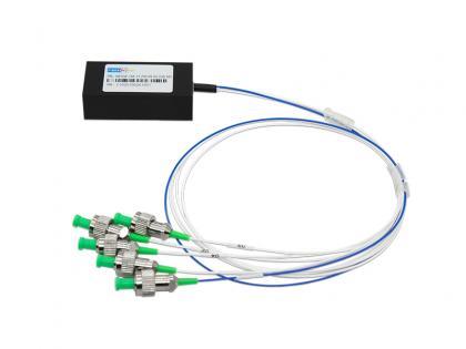 1X4 PM MEMS Optical Switch
 1650nm FBG Reflector SC/APC
 SFP 1.25G TX 1550 RX 1490 CWDM 180KM DDM Optical Transceiver

Address : Room 901, Building 6, JD Smart Industrial Park, No. 128, Juhua Stone Avenue, Huashan Town, Huadu District, Guangzhou City
Tel : +86 15989256178
Whatsapp : +86 15914235380
Email : sales@fiberwdm.com