
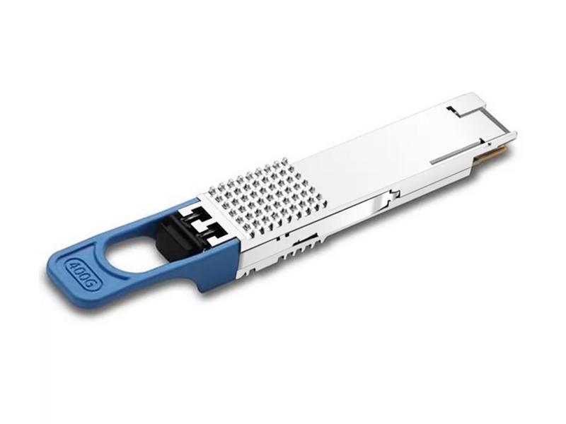
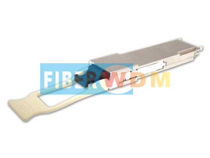
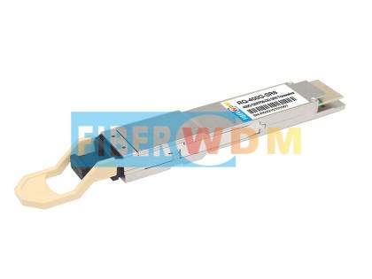
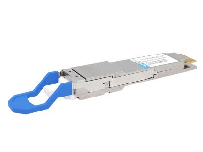
QSFP-DD 400G LR8 module are designed for 10 km optical communication applications, and it is compliant to IEEE 802.3cn for 400GE Ethernet. This module contains 8-lane optical transmitter, 8-lane optical receiver and module management block including 2 wire serial interfaces. The optical signals are multiplexed to a single-mode fiber through an industry standard LC connector. A block diagram is shown in Figure 1-1.
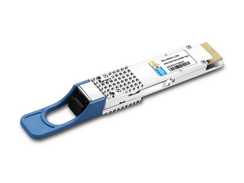
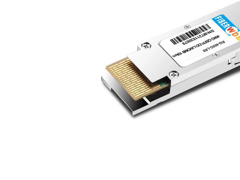
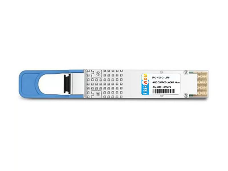
QSFP-DD 400G LR8 10km Optical Transceiver
RQ-400G-LR8
QSFP-DD 400G LR8 module are designed for 10 km optical communication applications, and it is compliant to IEEE 802.3cn for 400GE Ethernet. This module contains 8-lane optical transmitter, 8-lane optical receiver and module management block including 2 wire serial interfaces. The optical signals are multiplexed to a single-mode fiber through an industry standard LC connector. A block diagram is shown in Figure 1-1.
Figure 1-1 Transceiver block diagram

Pin Descriptions
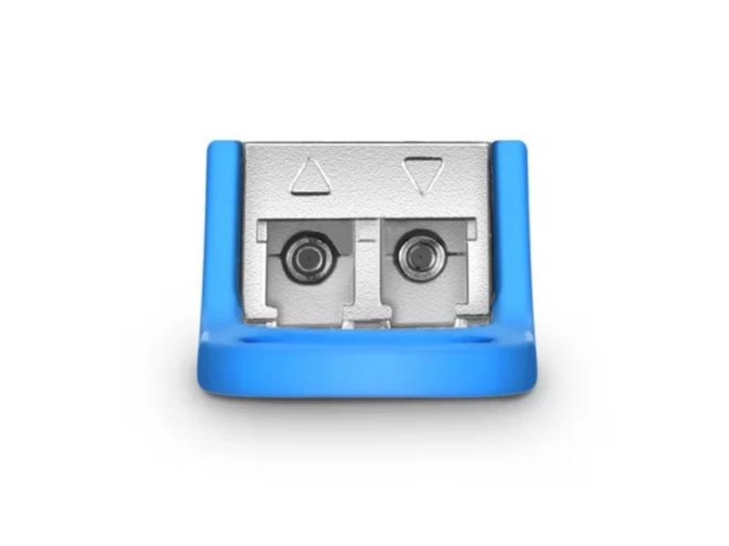
Figure 2-1 MSA compliant connector


Note:
1. QSFP-DD uses common ground (GND) for all signals and supply (power). All are comon within the QSFP-DD module and all module voltages are referenced to this po-te-nial unless otherwise noted. Connect these directly to the host board signal-common ground plane.
2. VccRx, VccRx1, Vcc1, Vcc2, VccTx and VccTx1 shall be applied concurrently.Requirements defined for the host side of the Host Card Edge Connector. VccRx, VccRx1, Vcc1, Vcc2, VccTx and VccTx1 may be internally connected within the module in any combination. The connector Vcc pins are each rated for a maximum current of 1000 mA.
3. All Vendor Specific, Reserved and No Connect pins may be terminated with 50ohms to ground on the host. Pad 65 (No Connect) shall be left unconnected within the module. Vendor specific and Reserved pads shall have an impedance to GND that is greater than 10K ohms and less than 100pF.
Absolute Maximum Ratings
It has to be noted that the operation in excess of any individual absolute maximum ratings might cause permanent damage to this module.

Operating Environments
Electrical and optical characteristics below are defined under this operating environment, unless otherwise specified.

Electrical Characteristics

Note: 400GAUI-8 Electrical Characteristics refers to CEI-56G-VSR-PAM4 of OIF-CEI-04.0.
Optical Characteristics
400GBASE-LR8 Operation (EOL, TOP = 0 to +70°C, VCC = 3.135 to 3.465 Volts)


Note: RS=max (-6.6, SECQ-8) dBm, BER@2E-4
EEPROM Definitions
Refer to QSFP-DD Common Management Interface Specification Rev 4.0.
3Digital Diagnostic Monitoring Functions
QSFP-DD 400G LR8 support the I2C-based Diagnostic Monitoring Interface (DMI) defined in document QSFP-DD Common Management Interface Specification Rev 4.0. The host can access real-time performance of transmitter and receiver optical power, temperature, supply voltage and bias current.

Note:
1. Actual temperature test point is fixed on module case around Laser Array.
2. Full operating temperature range.
Alarm and Warning Thresholds
QSFP-DD 400G LR8 support alarms function, indicating the values of the preceding basic performance are lower or higher than the thresholds.

Mechanical Specifications

Figure 10-1 Mechanical dimensions
Ordering Information

Want to know about this product?
If you are interested in our products and want to know more details,please leave a message here,we will reply you as soon as we can.
 400G QSFP-DD DR4 PAM4 1310nm 500M MPO Optical Transceiver
 400G QSFP-DD SR8 850nm MPO 100M Optical Transceiver
 400G QSFP-DD LR4 10KM Optical Transceiver
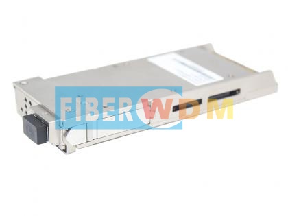 400G CFP2 DCO Optical Transceiver Module
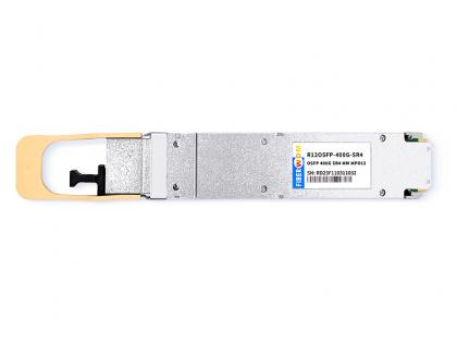
 QSFP112 400G BASE-SR4 850nm 100m Transceiver
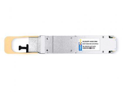
 400G OSFP SR4 MM MPO12 Optical Transceiver IB
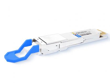
 400G OSFP DR4 SM MPO12 Optical Transceiver IB
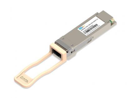
 400G QSFP-DD FR4 2KM Optical Transceiver

Address : Room 901, Building 6, JD Smart Industrial Park, No. 128, Juhua Stone Avenue, Huashan Town, Huadu District, Guangzhou City
Tel : +86 15989256178
Whatsapp : +86 15914235380
Email : sales@fiberwdm.com


