
Features
Semi-Active WDM System for 5G Fronthaul Transmission
Facilitates Rapid Deployment of 5G by Operators
1.1.Product Overview
After deploying 5G networks, the density of base stations will be 2 to 4 times that of 4G networks, and fiber constraints will be the main issue faced in 5G fronthaul deployment. To meet the rapid deployment of base stations and effectively save fiber resources in 4G and 5G network deployments, operators have adopted a solution combining WDM multiplexer and colored light modules to achieve low-cost, rapid coverage. However, there are also shortcomings and pain points in practical applications:
Passive WDM + colored light module mode has the following issues:
Solutions using active WDM or OTN technologies can solve the difficulties of network management and primary/backup route selection in optical paths, but they also face challenges such as high costs and difficulties in remote power supply.
Based on previous technical accumulations and research on active and passive WDM, and continuous in-depth understanding combined with customer pain points regarding fronthaul equipment carrying demands, Guangzhou Rui Dong has introduced a semi-active WDM as a solution for base station fronthaul.
The semi-active WDM solution uses active equipment on the local end and passive equipment on the remote end, facilitating deployment and maintenance. Through local equipment, it supports network management, line protection, and fast OTDR fault location functions. The maintenance methods are convenient and flexible, meeting high reliability requirements. This solution significantly alleviates the pressure on fiber resources, while also balancing cost, management, and protection advantages, thereby assisting operators in low-cost, high-bandwidth, and rapid deployment of 5G fronthaul networks.
This solution is suitable for scenarios with tight fiber resources at extended base stations, simple dual-star or bus-type network configurations (covering scenarios such as highways, high-speed railways, tunnels, bridges, etc.). It features colored light modules located on AAU and DU equipment, using WDM technology for transmission to save fiber resources and support OADM up/down wave functions. It can also utilize dual-route fiber cables for fronthaul service protection, while supporting legacy 4G fronthaul fibers, achieving unified fronthaul for 4G/5G.

Fig.1 Diagram of a semi-active WDM scheme
The networking architecture of semi-active wavelength division multiplexing (WDM) can be divided into star and bus topologies according to specific scenarios.

Figure 2 Semi-active WWD-star networking
 Figure 3 Semi-active WDM bus networking
Device view
|
Local End Equipment FW6600A device (1U4 slot active) |
Remote Combination and Division Module (Passive) |
|
|
19-inch rack (remote cabinet mounting) |
|
Local End Equipment FW6600C (4U16 slot active) |
Outdoor waterproof and dustproof box (remote wall/pole) |
2.1. Local End Equipment
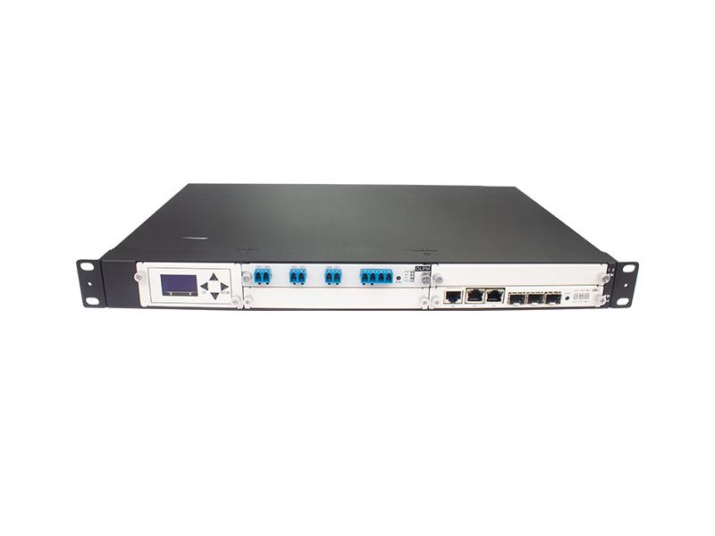
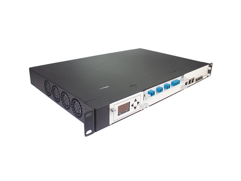
2.1.1.FW6600A - 1U Chassis
 1U Chassis Front View
 1U Chassis Back View
FW6600A is designed with a 1U standard 19-inch rack-mounted plug-in card structure, providing 4 business slots, 1 main control card slot, 1 fan slot, and 2 power slots (at the rear). It uses a front panel outlet method, with all optical interfaces and network management interfaces designed on the front;
The FW6600A-type 1U chassis has four service slots, and the NMS card occupies one slot, and can be inserted into a maximum of three service cards, which can support convergence in three optical directions
Technical Specifications of FW6600A 1U Chassis
|
The name of the metric |
metrics |
|
|
Dimensions: |
482(W)×44(H)×320(D)(mm) |
|
|
Weight (fully loaded) |
7.5kg |
|
|
TypicalPowerConsumption |
<30W |
|
|
Protection Features |
Hot-swappable NE management card without affecting existing services when failing |
|
|
StandardOperating Voltage: |
DC |
-36 V-72V |
|
AC |
90V -260V |
|
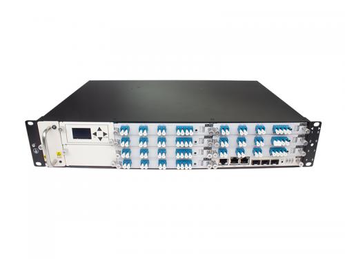
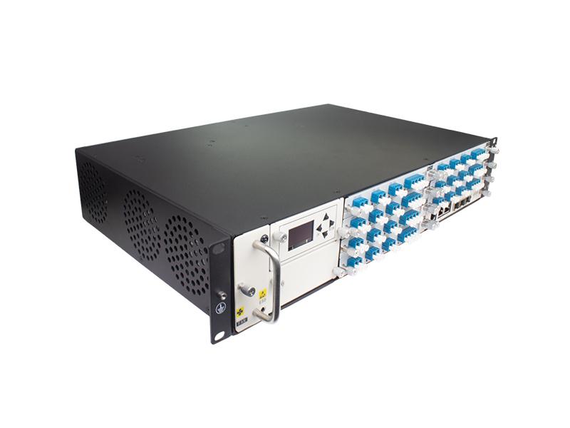
2.1.2 FW6600B - 2U Chassis

2U Chassis Front View
 2U Chassis Back View
FW6600B is designed with a 2U standard 19-inch rack-mounted plug-in card structure, providing 8 business slots, 1 main control card slot, 1 fan slot, and 2 power slots (at the rear). It uses a front panel outlet method, with all optical interfaces and network management interfaces designed on the front;
The FW6600B-type 2U chassis has 8 service slots, and the NMS card occupies 1 slot, and can be inserted into a maximum of 7 service cards, which can support convergence in 7 optical directions
Technical Specifications of FW6600B 2U Chassis
|
The name of the metric |
metrics |
|
|
Dimensions |
486(W)×86(H)×352(D)(mm) |
|
|
Weight (fully loaded) |
13.5kg |
|
|
TypicalPowerConsumption |
<50W |
|
|
Protection Features |
Hot-swappable NE management card without affecting existing services when failing |
|
|
StandardOperating Voltage: |
DC |
-36 V-72V |
|
AC |
90V -260V |
|
2.1.3 FW6600C -4U chassis
 4U chassis front
 4U chassis back
The FW6600C chassis adopts a 4U standard 19-inch rack-mount and plug-in card structure, and provides 16 service slots, 1 main control board slot, 1 fan slot, and 2 power supply slots in a single chassis. The front panel cable outlet mode is adopted, and all optical interfaces, power supply and network management interfaces are designed on the front;
The FW6600C-type 4U chassis has 16 service slots, and the NMS card occupies 1 slot, and can insert up to 15 service boards, which can support the convergence of 15 optical directions
FW6600C 4U Chassis specifications
|
The name of the metric |
metrics |
|
|
Dimensions |
483(W)×178(H)×280(D)(mm) |
|
|
Weight (fully loaded) |
15.5kg |
|
|
TypicalPowerConsumption |
<80W |
|
|
Protection Features |
Hot-swappable NE management card without affecting existing services when failing |
|
|
StandardOperating Voltage: |
DC |
-36 V -72V |
|
AC |
90V -260V |
|
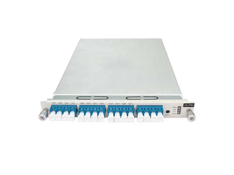
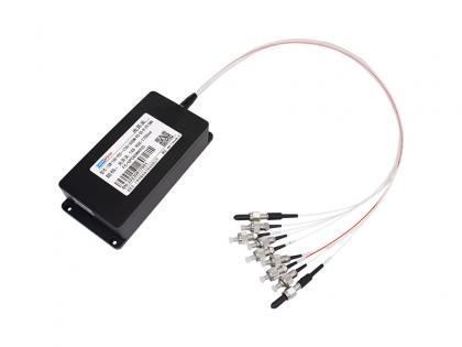
2.1.4 6 waves of Local End Equipment Mux&DeMux

Functional structure:

6 waves of Local End Equipment Mux&DeMux Functional structure (with optical power monitoring and optical protection)
Optical performance indicators
|
parameter |
unit |
index |
|
Number of channels |
|
6 |
|
Center wavelength |
nm |
1271、 1291、 1311、 1331、 1351、 1371 |
|
Center wavelength deviation |
nm |
±1.5 |
|
-1dB channel bandwith |
nm |
>14 |
|
Banding flatness |
dB |
<0.5 |
|
Mux&DeMux Channel insertion loss(without Optical Protection) |
dB |
<1.8 |
|
Mux&DeMux Channel insertion loss(with Optical Protection) |
dB |
<3.5 |
|
Mux&DeMux Channel insertion loss uniformity |
dB |
<1.0 |
|
Adjacent channel isolation |
dB |
>25 |
|
Non-adjacent channel isolation |
dB |
>35 |
|
Wavelength Heat stability |
nm/℃ |
<0.002 |
|
Insertion loss heat stability |
dB/℃ |
<0.007 |
|
Polarization-related losses |
dB |
<0.2 |
|
Return loss |
dB |
≥45 |
|
Working temperature |
℃ |
-40~+85 |
|
Storage temperature |
℃ |
-40~+85 |
|
Working humidity |
|
5%~95% RH, No condensation |
|
The number of slots in the chassis |
|
1slot |
|
OTDR monitoring port |
|
With OTDR monitoring port (wavelength 1625/1650nm) optional |
|
Optical protection |
|
It can provide single-fiber main and standby optical path protection |
|
Optical protection switching time |
|
<20ms |
|
Optical power detection range |
|
-50 dBm ~+25dBm |
|
Optical interface |
|
LC/UPC |
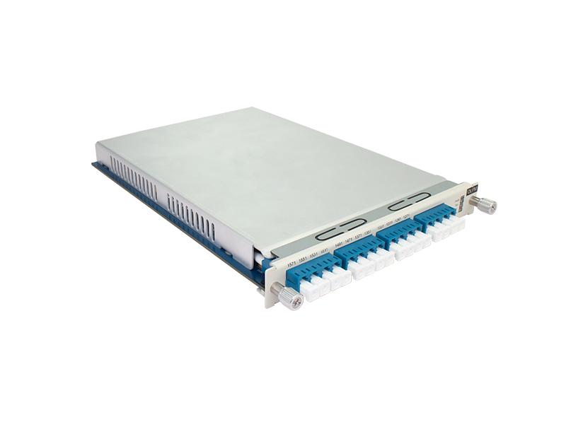
2.1.5 12 waves remote passive WDM Mux&DeMux

Product illustration:

12 waves remote passive WDM Mux&DeMux(optical protection)
Optical performance indicators
|
parameter |
unit |
index |
|
Number of channels |
|
12 |
|
Center wavelength |
nm |
1271、 1291、 1311、 1331、 1351、 1371、1471、 1491、 1511、 1531、 1551、 1571 |
|
Center wavelength deviation |
nm |
±1.5 |
|
-1dB channel bandwith |
nm |
>14 |
|
Banding flatness |
dB |
<0.5 |
|
Mux&DeMux Channel insertion loss(without Optical Protection) |
dB |
<2.2 |
|
Mux&DeMux Channel insertion loss(with Optical Protection) |
dB |
<3.5 |
|
Mux&DeMux Channel insertion loss uniformity |
dB |
<1.2 |
|
Adjacent channel isolation |
dB |
>25 |
|
Non-adjacent channel isolation |
dB |
>35 |
|
Wavelength Heat stability |
nm/℃ |
<0.002 |
|
Insertion loss heat stability |
dB/℃ |
<0.007 |
|
Polarization-related losses |
dB |
<0.2 |
|
Return loss |
dB |
≥45 |
|
Working temperature |
℃ |
-40~+85 |
|
Storage temperature |
℃ |
-40~+85 |
|
Working humidity |
|
5%~95% RH, No condensation |
|
The number of slots in the chassis |
|
1slot |
|
OTDR monitoring port |
|
With OTDR monitoring port (wavelength 1625/1650nm) optional |
|
Optical protection |
|
It can provide single-fiber main and standby optical path protection |
|
Optical protection switching time |
|
<20ms |
|
Optical power detection range |
|
-50 dBm ~+25dBm |
|
Optical interface |
|
LC/UPC |
Want to know about this product?
If you are interested in our products and want to know more details,please leave a message here,we will reply you as soon as we can.
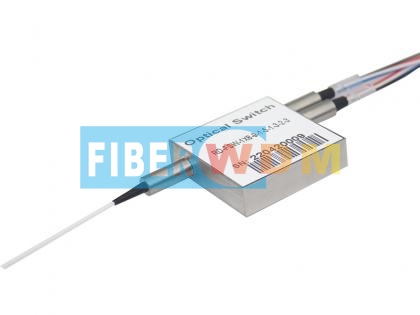
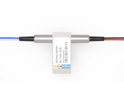 2x2 Bypass Mechanical Optical Switch
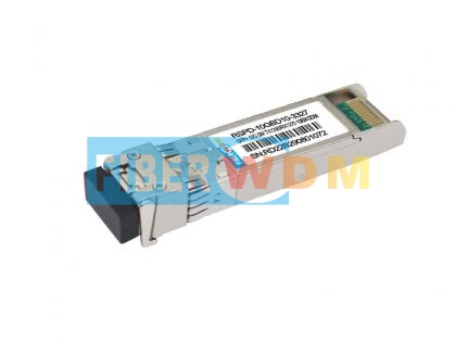 SFP+ 10G BIDI 10KM 1270/1330nm Optical Transceiver
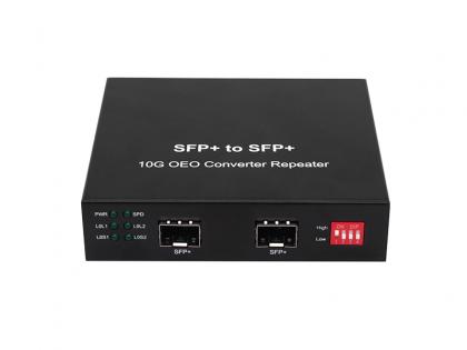 10G SFP+ Converter
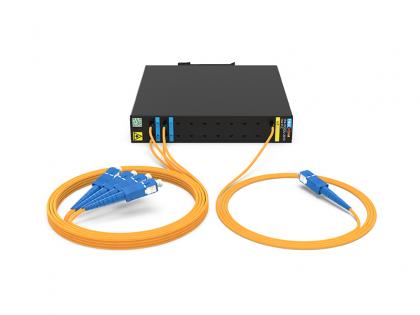 1x4 PLC SC/UPC 2.0MM 1.0M Fiber DIN Mounting Box 120*110*20MM
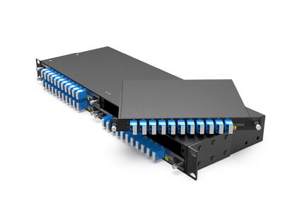
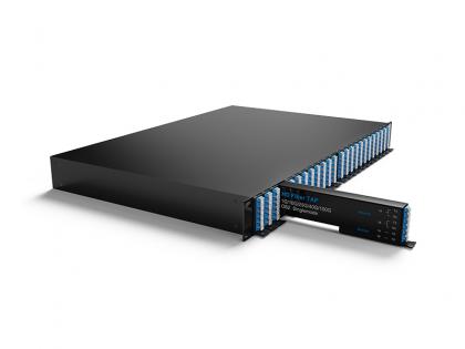 24* OTAPs Passive Network Optical Taps LC/UPC 1U Rack
 1X8 900-1700nm 300um Optical Switch
 1x8 Mechanical Optical Switch
 150GHz 8CH DWDM MUX DEMUX C38-H48(1556.555nm-1548.115nm) with Monitor Port,LC/UPC,LGX Box, and 4 Slots 1U Rack

Address : Room 901, Building 6, JD Smart Industrial Park, No. 128, Juhua Stone Avenue, Huashan Town, Huadu District, Guangzhou City
Tel : +86 15989256178
Whatsapp : +86 15914235380
Email : sales@fiberwdm.com


 Local End Equipment FW6600B (2U8 slot active)


