
Features
QSFP56 Serial Optical Interface
4x50G PAM4 retimed 200GAUI-4 C2M electrical interface
QSFP MSA Compliant
Support Protocol
Low Power Consumption
Applications
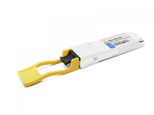
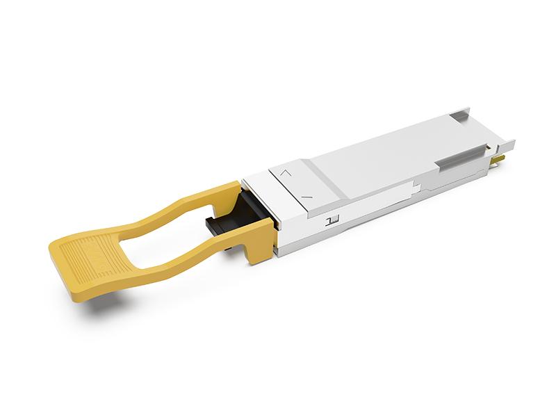
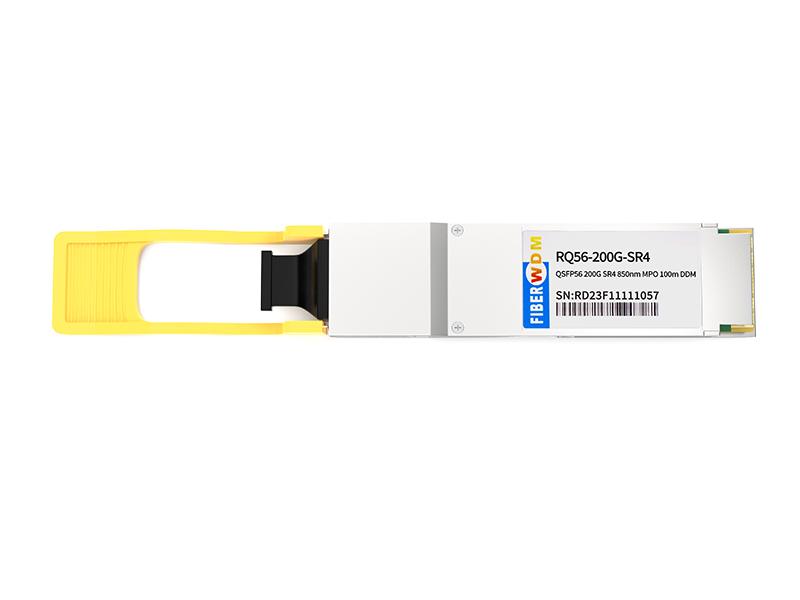
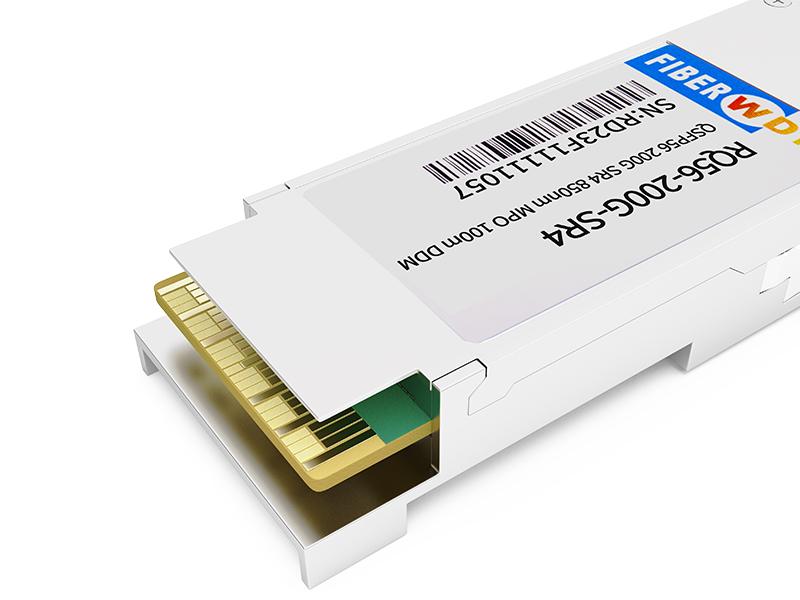
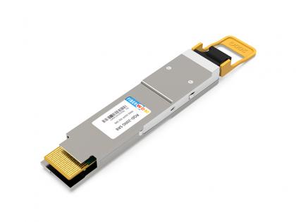
200G QSFP56 SR4 100m 850nm MPO PM4 Optical Transceiver
Functional Block Diagram

General Description
200G QSFP56 SR4 Optical Transceiver modules are designed for use in 200Gigabit Ethernet links over OM3/OM4 multimode fiber. They are compliant with the QSFP MSA and with IEEE 802.3cd 200GBASE-SR4 specification. Digital diagnostics functions are available via the I2C interface as specified by SFF-8636.The transceiver is RoHS 2.0 compliant and lead-free per Directive 2011/65/EU.
Absolute Maximum Ratings
|
Parameter |
Symbol |
Min |
Max |
Unit |
|
Storage Temperature |
Ts |
-40 |
85 |
℃ |
|
Relative Humidity (non-condensation) |
RH |
|
85 |
% |
|
Supply Voltage |
Vcc |
-0.5 |
3.6 |
V |
|
Receiver Damage Threshold, per Lane |
PR dmg |
5 |
|
dBm |
Recommended Operating Conditions
|
Parameter |
Symbol |
Min |
Max |
Unit |
|
Operating Case Temperature |
Top |
0 |
70 |
℃ |
|
Power Supply Voltage |
Vcc |
3.135 |
3.465 |
V |
|
Total Power Consumption |
Pc |
|
5 |
W |
|
Bit Rate |
BR |
|
212.5 |
Gbps |
|
Fiber Length on OM3 MMF |
|
|
70 |
m |
|
Fiber Length on OM4 MMF |
|
|
100 |
m |
Transmitter Optical Interface
|
Parameter |
Symbol |
Min |
Typical |
Max |
Unit |
|
Data rate per lane |
DR |
|
26.5625 |
|
Gbd |
|
Modulation format |
|
PAM4 |
|
||
|
Center Wavelength |
λ |
840 |
850 |
868 |
nm |
|
RMS spectral width |
σ |
|
|
0.65 |
nm |
|
Average Launch power, each lane |
Pavg |
-6.5 |
|
4 |
dBm |
|
Optical Power OMA, each Lane |
PoMA |
-4.5 |
|
3 |
dBm |
|
Launch power in OMA outer minus TDECQ |
|
-5.9 |
|
|
dBm |
|
Transmitter and dispersion eye closure (TDECQ), each lane |
TDECQ |
|
|
4.5 |
dB |
|
Extinction ratio |
ER |
3 |
|
|
dB |
|
Optical Return Loss Tolerance |
ORLT |
|
|
12 |
dB |
|
Optical Power for TX DISABLE |
|
|
|
-30 |
dBm |
|
Encircled fluxb¹ |
|
≥86%at 19 um ≤30%at 4.5 um |
|
||
Notes:
1.Measured into type A1a.2 or type A1a.3, or A1a.4,50 um fiber, in accordance with IEC 61280-1-4
Receiver Optical Interface
|
Parameter |
Symbol |
Min |
Typical |
Max |
Unit |
|
|
Data rate per lane |
BR |
|
26.5625 |
|
Gbd |
|
|
Modulation format |
|
PAM4 |
|
|||
|
Damage threshold |
|
5 |
|
|
dBm |
|
|
Average receive power, each lane |
|
-8.4 |
|
4 |
dBm |
|
|
Receiver reflectance |
Rr |
|
|
-12 |
dB |
|
|
Receiver sensitivity, each lane¹ |
|
RS=max (-6.5, SECQ-7.9) |
dBm |
|||
|
Stressed receiver sensitivity, each ane |
|
|
|
-3.4 |
dBm |
|
|
Rx LOS |
Assert |
|
-30 |
|
|
dBm |
|
De-assert |
|
|
|
-9 |
dBm |
|
|
Hysteresis |
|
0.5 |
|
|
dB |
|
Notes:
1.Receiver sensitivity is informative and is defined for a transmitter with a value of SECQ. Measured with conformance test signal at TP3 for BER = 2.4E-4 Pre-FEC.
High speed Electrical Specifications
|
Parameters |
Min |
Typical |
Max |
Unit |
|
Supply voltage |
3.135 |
|
3.465 |
V |
|
Supply Current |
|
|
1.59 |
A |
|
Input differential impedance |
90 |
100 |
110 |
Ω |
|
Differential pk-pk input Voltage Tolerance |
900 |
|
|
mVpp |
|
Differential data output swing |
|
|
900 |
mVpp |
|
Bit Error Rate Pre-FEC |
|
|
2.4E-4 |
|
|
Input Logic Level High |
2 |
|
Vcc |
V |
|
Input Logic Level Low |
0 |
|
0.8 |
V |
|
Output Logic Level High |
Vcc-0.5 |
|
Vcc |
V |
|
Output Logic Level Low |
0 |
|
0.4 |
V |
PIN Definitions
QSFP56 pin-out as being defined by QSFP MSA,PIN Descriptions are as follows:

Package dimensions
shows the package dimensions of the module. Package dimensions are specified in QSFP MSA.

Ordering Information
|
Part Number |
Temperature Range |
Distance |
Fiber Type |
E/O |
O/E |
|
RQ56-200G-SR4 |
0 to 70℃ |
100m |
MMF |
VCSEL 850nm |
PIN |
Want to know about this product?
If you are interested in our products and want to know more details,please leave a message here,we will reply you as soon as we can.
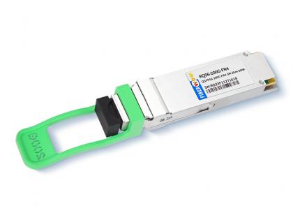 200G QSFP56 FR4 2KM LC PAM4 Optical Transceiver
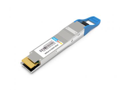 200Gb/s QSFP DD PSM8 10km Optical Transceiver
 200G QSFP-DD SR8 100m Optical Transceiver
 QSFPDD 200G 2xCWDM4 2km Optical Transceiver
 QSFPDD 200G PSM8 10km Optical Transceiver (MPO16)
 100G QSFP28 BIDI 1271nm/1331nm 10km Transceiver
 3G Video SFP Optical Transceiver support 1080P 60HZ Video
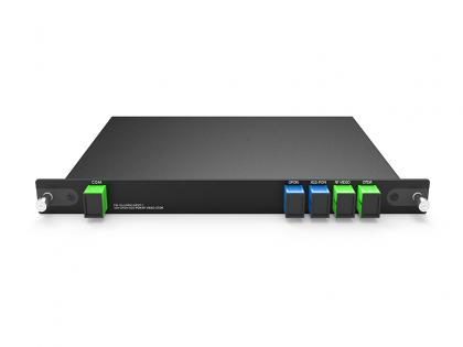 4CH WDM GPON XGS-PON RF Video And OTDR Plug-in LGX Box 215*150*20MM

Address : Room 901, Building 6, JD Smart Industrial Park, No. 128, Juhua Stone Avenue, Huashan Town, Huadu District, Guangzhou City
Tel : +86 15989256178
Whatsapp : +86 15914235380
Email : sales@fiberwdm.com


