

Product Features
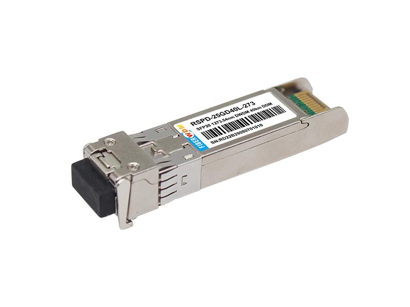
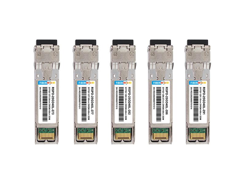
25Gbps SFP28 LAN-WDM Transceiver, DML&APD Single Mode, 40km Reach
RSPD-25GDL40-XXX
Applications
Description
The SFP28 transceivers are high performance, cost effective modules supporting data rate of 25.78Gbps and 40km transmission distance with SMF.
The transceiver consists of three sections: a cooled DML laser transmitter, a APD photodiode integrated with a trans-impedance preamplifier (TIA) and MCU control unit. All modules satisfy class I laser safety requirements.
The transceivers are compatible with SFP Multi-Source Agreement and SFF-8472 digital diagnostics functions.

Transceiver functional diagram
Absolute Maximum Ratings
|
Parameter |
Symbol |
Min. |
Typ. |
Max. |
Unit |
|
Storage Temperature |
Ts |
-40 |
- | 85 | ℃ |
|
Relative Humidity |
RH |
5 |
- | 95 | % |
|
Power Supply Voltage |
VCC |
-0.3 | - | 4 | V |
|
Signal Input Voltage |
VSI |
Vcc-0.3 |
- |
Vcc+0.3 |
V |
Recommended Operating Conditions
|
Parameter |
Symbol |
Min. |
Typ. |
Max. |
Unit |
Note |
|
Case Operating Temperature |
Tcase |
0 |
70 |
℃ | ||
|
Power Supply Voltage |
VCC |
3.14 | 3.3 | 3.47 | V | |
|
Power Supply Current |
ICC |
600 |
mA |
|||
|
Data Rate |
BR |
25.78 |
Gbps |
TX Rate/RX Rate |
||
|
Transmission Distance |
TD | 40 | Km | |||
|
Coupled fiber |
Single mode fiber |
9/125um SMF |
||||
Optical Characteristics
|
Parameter |
Symbol |
Min. |
Typ. |
Max. |
Unit |
Note |
|
Transmitter |
||||||
|
Lane Wavelengths(Range) |
1272.55 to 1274.54 1276.89 to 1278.89 1281.25 to 1283.27 1285.65 to 1287.69 1290.07 to 1292.12 1294.53 to 1296.59 1299.02 to 1301.09 1303.54 to 1305.63 1308.09 to 1310.19 |
nm | ||||
|
Average Launched Power |
PO |
0 | - | +6.0 |
dBm |
|
|
Average Launched Power(Laser Off) |
Poff |
- | - |
-30 |
dBm |
|
|
Spectrum Bandwidth(-20dB) |
Dl |
- | - | 1 | nm | |
|
Side-Mode Suppression Ratio |
SMSR |
30 | - | - | dB | |
|
Transmitter and Dispersion Penalty |
TDP | - | - | 1 | dB | |
|
Extinction Ratio |
ER | 3.5 | - | - | dB | |
|
Output Eye Mask |
Compliant with IEEE 802.3cc |
Note (2) |
||||
|
Receiver |
||||||
|
Input Optical Wavelength |
λIN |
1272.55 | 1310.19 | nm | ||
|
Receiver Sensitivity-AVG |
PSens |
-19 |
dBm |
Note (1) |
||
|
Receiver Sensitivity-OMA |
PSens-OMA |
-18.2 |
dBm |
Note (1) |
||
|
Input Saturation Power (Overload) |
PSAT |
-4 |
dBm |
Note (1) |
||
|
Receiver Reflectance |
-26 |
dB |
||||
|
Los Of Signal Assert |
PA |
-30 |
dBm |
|||
|
Los Of Signal De-assert |
PD |
-20 |
dBm |
|||
|
LOS -Hysteresis |
PHys |
0.5 |
dB |
|||
Note:
Note (1): BER≤5x10⁻⁵
Electrical Interface Characteristics
High Speed Electrical Interface Characteristics
|
Parameter |
Symbol |
Min |
Typ |
Max |
Unit |
Notes |
|
Transmitter |
||||||
|
Differential input swing |
Vin(pp) |
190 | 700 |
mV |
||
|
Differential input return loss (min) |
RLd(f) |
9.5–0.37f, 0.01≤f<8 4.75–7.4log10(f/14), 8 ≤f<19 |
dB |
|||
|
Differential to common mode input return loss (min) |
RLdc(f) |
22-20(f/25.78), 0.01≤f<12.89 15-6(f/25.78), 12.89≤f<19 |
dB |
|||
|
Differential termination mismatch |
Tm |
10 | % | |||
|
Eye width |
Ew |
0.46 |
UI |
|||
|
Applied pk-pk sinusoidal jitter |
Ppj |
Per IEEE 802.3bm |
||||
|
Eye height |
Eh |
95 |
mV |
|||
|
DC common mode voltage |
DCv |
-350 |
2850 |
mV |
||
|
Receiver |
||||||
|
Differential data output swing |
Vout(pp) |
300 |
- | 850 |
mV |
- |
|
Eye width |
Ew |
0.57 |
- | - |
UI |
- |
|
Vertical eye closure |
Vec |
- |
- | 5.5 |
dB |
- |
|
Differential output return loss (min) |
RLd(f) |
9.5–0.37f, 0.01≤f<8 4.75–7.4log10(f/14), 8 ≤f<19 |
dB |
- | ||
|
Common to differential mode conversion return loss (min) |
RLdc(f) |
22-20(f/25.78), 0.01≤f<12.89 15-6(f/25.78), 12.89≤f<19 |
dB |
- | ||
|
Differential termination mismatch |
Tm |
- |
- | 10 |
% |
- |
|
Transition time, 20% to 80% |
Tr/Tf |
12 |
- | - |
ps |
20%~80% |
LOW Speed Electrical Interface Characteristics
|
Parameter |
Symbol |
Min. |
Typ. |
Max. |
Unit |
|
Transmitter |
|||||
|
Transmitter Fault Output-High |
VFaultH |
2 | - |
Vcc+0.3 |
V |
|
Transmitter Fault Output-Low |
VFaultL |
0 | - | 0.8 |
V |
|
Transmitter Disable Voltage- High |
VDisH |
2 | - |
Vcc+0.3 |
V |
|
Transmitter Disable Voltage- low |
VDisL |
0 | - | 0.8 |
V |
|
Receiver |
|||||
|
LOS Output Voltage-High |
VLOSH |
2 | - |
Vcc+0.3 |
V |
| LOS Output Voltage-Low |
VLOSL |
0 | - | 0.8 |
V |
Timing and Electrical
|
Parameter |
Symbol |
Min |
Typical |
Max |
Unit |
|
Tx Disable Negate Time |
t_on |
1 |
ms |
||
|
Tx Disable Assert Time |
t_off |
10 |
µs |
||
|
Time To Initialize, including Reset of Tx Fault |
t_init |
300 |
ms |
||
|
Tx Fault Assert Time |
t_fault |
100 |
µs |
||
|
Tx Disable To Reset |
t_reset |
10 |
µs |
||
|
LOS Assert Time |
t_loss_on |
100 |
µs |
||
|
LOS De-assert Time |
t_loss_off |
400 |
µs |
||
|
Serial ID Clock Rate |
f_serial_clock |
100 | 400 |
KHz |
|
|
MOD_DEF (0:2)-High |
VH |
2 |
Vcc |
V |
|
|
MOD_DEF (0:2)-Low |
VL |
0.8 |
V |
Diagnostics
|
Parameter |
Range |
Unit |
Accuracy |
Calibration |
|
Temperature |
0 to 70 |
℃ |
±3°C |
Internal |
|
Voltage |
3.0 to 3.6 |
V |
±3% |
Internal |
|
Bias Current |
0 to 100 |
mA |
±10% |
Internal |
|
TX Power |
0 to 6 |
dBm |
±3dB |
Internal |
|
RX Power |
-19 to -4 |
dBm |
±3dB |
Internal |
Digital Diagnostic Memory Map
The transceivers provide serial ID memory contents and diagnostic information about the present operating conditions by the 2-wire serial interface (SCL, SDA).
The diagnostic information with internal calibration or external calibration all are implemented, including received power monitoring, transmitted power monitoring, bias current monitoring, supply voltage monitoring and temperature monitoring.
The digital diagnostic memory map specific data field defines as following.

Pin Descriptions

|
Pin |
Signal Name |
Description |
Plug Seq. |
Notes |
| 1 |
VEET |
Transmitter Ground |
1 | |
| 2 |
TX FAULT |
Transmitter Fault Indication |
3 |
Note 1 |
| 3 |
TX DISABLE |
Transmitter Disable |
3 |
Note 2 |
| 4 |
SDA |
SDA Serial Data Signal |
3 | |
| 5 |
SCL |
SCL Serial Clock Signal |
3 | |
| 6 |
MOD_ABS |
Module Absent. Grounded within the module |
3 | |
| 7 |
RS0 |
Not Connected |
3 | |
| 8 |
LOS |
Loss of Signal |
3 |
Note 3 |
| 9 |
RS1 |
Not Connected |
3 | |
| 10 |
VEER |
Receiver ground |
1 | |
| 11 |
VEER |
Receiver ground |
1 | |
| 12 |
RD- |
Inv. Received Data Out |
3 |
Note 4 |
| 13 |
RD+ |
Received Data Out |
3 |
Note 4 |
| 14 |
VEER |
Receiver ground |
1 | |
| 15 |
VCCR |
Receiver Power Supply |
2 | |
| 16 |
VCCT |
Transmitter Power Supply |
2 | |
| 17 |
VEET |
Transmitter Ground |
1 | |
| 18 |
TD+ |
Transmit Data In |
3 |
Note 5 |
| 19 |
TD- |
Inv. Transmit Data In |
3 |
Note 5 |
| 20 |
VEET |
Transmitter Ground |
1 |
Notes:
Plug Seq.: Pin engagement sequence during hot plugging.
1) TX Fault is an open collector output, which should be pulled up with a 4.7k~10kΩ resistor on the host board to a voltage between 2.0V and Vcc+0.3V. Logic 0 indicates normal operation; Logic 1 indicates a laser fault of some kind. In the low state, the output will be pulled to less than 0.8V.
2) Laser output disabled on TDIS >2.0V or open, enabled on TDIS <0.8V.
3) LOS is open collector output. Should be pulled up with 4.7k~10kΩ on host board to a voltage between 2.0V and 3.6V. Logic 0 indicates normal operation; logic 1 indicates loss of signal.
4) RD-/+: These are the differential receiver outputs. They are internally AC-coupled 100 differential lines which should be terminated with 100Ω (differential) at the user SERDES.
5) TD-/+: These are the differential transmitter inputs. They are internally AC-coupled, differential lines with 100Ω differential termination inside the module.
Recommended Interface Circuit

Mechanical Dimensions

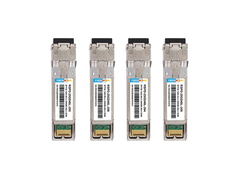
Ordering information
|
Part Number |
Product Description |
|
RSPD-25GD40L-273 |
SFP28 1273.54nm LAN-WDM, 25.78Gbps, LC, 40km, 0°C~+70°C, with DDM |
|
RSPD-25GDL40-277 |
SFP28 1277.89nm LAN-WDM, 25.78Gbps, LC, 40km, 0°C~+70°C, with DDM |
|
RSPD-25GDL40-282 |
SFP28 1282.26nm LAN-WDM, 25.78Gbps, LC, 40km, 0°C~+70°C, with DDM |
|
RSPD-25GDL40-286 |
SFP28 1286.67nm LAN-WDM, 25.78Gbps, LC, 40km, 0°C~+70°C, with DDM |
|
RSPD-25GDL40-291 |
SFP28 1291.10nm LAN-WDM, 25.78Gbps, LC, 40km, 0°C~+70°C, with DDM |
|
RSPD-25GDL40-295 |
SFP28 1295.56nm LAN-WDM, 25.78Gbps, LC, 40km, 0°C~+70°C, with DDM |
|
RSPD-25GDL40-300 |
SFP28 1300.05nm LAN-WDM, 25.78Gbps, LC, 40km, 0°C~+70°C, with DDM |
|
RSPD-25GDL40-304 |
SFP28 1304.58nm LAN-WDM, 25.78Gbps, LC, 40km, 0°C~+70°C, with DDM |
|
RSPD-25GDL40-309 |
SFP28 1309.14nm LAN-WDM, 25.78Gbps, LC, 40km, 0°C~+70°C, with DDM |
Want to know about this product?
If you are interested in our products and want to know more details,please leave a message here,we will reply you as soon as we can.
 25Gbps SFP28 CWDM 1271~1371nm Duplex 10km Transceiver
 25G SFP28 MWDM Optical Transceiver
25G SFP28 LWDM Optical Transceiver
25G SFP28 DWDM Optical Transceiver
25G SFP28 MWDM Optical Transceiver
25G SFP28 LWDM Optical Transceiver
25G SFP28 DWDM Optical Transceiver
 25G SFP28 BIDI Optical Transceiver
25G SFP28 Optical Transceiver
25G SFP28 BIDI Optical Transceiver
25G SFP28 Optical Transceiver
 SFP 1.25G 1550nm 200KM DDM Optical Transceiver
 Dual Fiber 8CH C21-C28 DWDM MUX DEMUX

Address : Room 901, Building 6, JD Smart Industrial Park, No. 128, Juhua Stone Avenue, Huashan Town, Huadu District, Guangzhou City
Tel : +86 15989256178
Whatsapp : +86 15914235380
Email : sales@fiberwdm.com


